High-speed shear for transversely cutting rolled strip

a technology of transverse cutting and rolling strip, which is applied in the field of high-speed shear with a knife, can solve the problems of not being designed for such high strip speed, rotary shear, and increasing the demand for significantly higher speeds

Inactive Publication Date: 2006-09-19
SMS SCHLOEMANN SIEMAG AG
View PDF11 Cites 18 Cited by
  • Summary
  • Abstract
  • Description
  • Claims
  • Application Information

AI Technical Summary

Benefits of technology

[0012]Therefore, starting from the prior art discussed above, it is the primary object of the present invention to further develop a high-speed shear for cutting hot-rolled and cold-rolled strip while avoiding the aforementioned difficulties and technical limits in such a way that exact cuts are safely ensured at strip speeds of up to 30 m / sec., even in the case of minimum strip thicknesses. This is to be achieved while avoiding an overloading of knife, and / or of the surface portion of the counter-drum, of the adjusting mechanisms and the bearings of the drum, and / or to avoid an incomplete cut.
[0016]Both technical solutions achieve the same result, namely the knife which initially protrudes out of the cutting circle can yield during the cutting process when meeting the anvil, or the surface of the second drum serving as an anvil, to such an extent that an impermissible increase of the cutting forces and, thus, wear phenomena at all structural components of the cutting elements or adjusting device and including the bearings of the drum can be safely avoided.
[0019]The interaction between the chisel-type knife and the anvil drum provides the advantage that the synchronization of the circumferential speeds of both drums does not have to be particularly precise. On the contrary, in the case of a difference of the circumferential speeds of the chisel-type knife and the anvil drum, the entire circumference of the anvil drum can be utilized in the interaction of the knife so that a wear distribution is achieved and the availability of the shear is favorably improved.

Problems solved by technology

Rotary shears or guillotine shears which are conventional in the art and serve to cut hot-rolled wide strip, are not designed for such high strip speeds.
However, flying shears which are used following cold-rolling tandem trains usually operate today only at strip speeds of about 6 m / sec; in these type of shears there is also a demand for significantly higher speeds.
At such high strip speeds, it is no longer possible to economically carry out the conventional cutting procedures in which the knife drum is accelerated to a strip speed of up to 30 m / sec. for carrying out the cut and in which the knife drum must subsequently be decelerated again.
However, when the shear has this configuration, a safe and exact cut can only be ensured if the cutting gap between the knife cutting edge and the anvil or the surface portion of the counter-drum is zero.
If this is not the case, for example, if the knife has an excess length, the knife and the anvil may be overloaded until they are destroyed, or when the knife has an insufficient length the cut remains incomplete.
However, due to one or more interacting variables including thermal extension, wear, elastic behavior of the adjusting devices, acceleration forces, finishing tolerances, etc. the adjustment of the cutting gap to “zero” cannot be achieved with the required certainty.
However, this protrusion leads to a rapid increase of the cutting forces and, thus, to wear phenomena in all structural components of the cutting elements, the adjusting device and the bearings of the drums.

Method used


Image

  • High-speed shear for transversely cutting rolled strip
  • High-speed shear for transversely cutting rolled strip
  • High-speed shear for transversely cutting rolled strip

Examples


Embodiment Construction

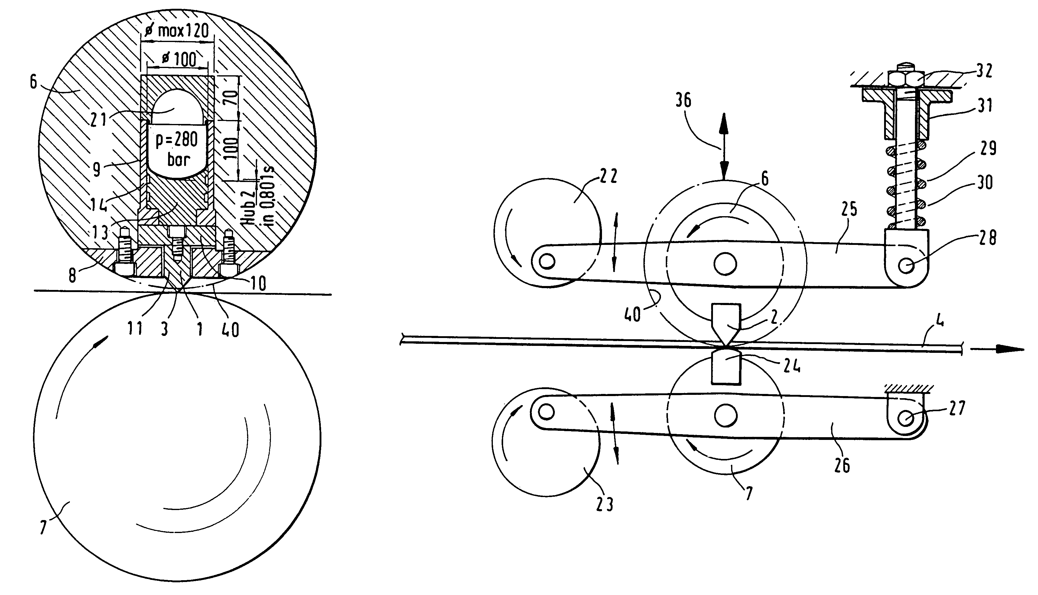
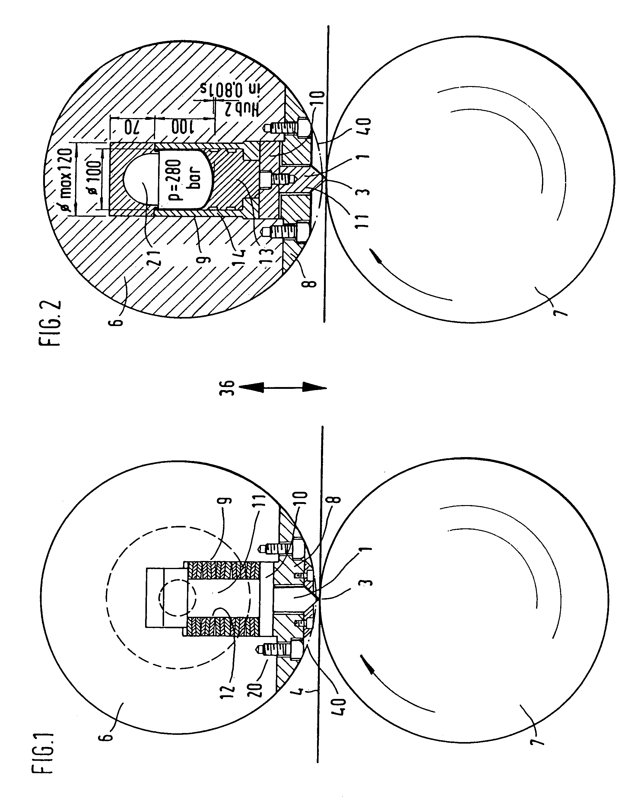
[0031]FIG. 1 of the drawing shows a flying high-speed shear with knife drum 6 and an anvil drum 7 which interacts with the knife drum 6 for cutting a rolled strip 4. The two drums 6, 7 can be accelerated by means of a drive device, not shown, to the feeding speed of the rolled strip 4 to be cut and are adjustable relative to each other for performing a cut by means of an adjusting device 36 which is known in the art and is illustrated in FIG. 5. By means of such an adjusting device the two drums 6, 7 are accelerated independently of the adjusting procedure for carrying out a cut to a circumferential speed which corresponds to the feeding speed of the strip 4 to be cut and the two drums are maintained during the further duration of operation at this circumferential speed, while the adjustment for carrying out the cut is reversed immediately after a cut has been carried out into an open neutral position, so that a predetermined length of the strip can pass through the shear uncut.

[003...


PUM

PropertyMeasurementUnit
speedsaaaaaaaaaa
thicknessesaaaaaaaaaa

Abstract

A high-speed shear with a knife, particularly a chisel-type knife with a knife edge, arranged on at least one of two oppositely arranged drums, wherein the knife can be accelerated to the feeding speed of the rolled strip and the drums can be adjusted relative to each other for carrying out a cut. At least one drive unit provided for the drums serves to accelerate the drums to the speed of the rolled strip to be cut and at least one of the drums may be provided with a separately controllable adjusting device. The chisel-type knife of the knife drum is mounted so as to protrude from the cutting circle towards the anvil or the surface portion of the second drum acting as an anvil and to mount the chisel-type knife of the knife drum so as to be resiliently supported against a predetermined restoring force.

Description

BACKGROUND OF THE INVENTION[0001]1. Field of the Invention[0002]The present invention relates to a high-speed shear with a knife, particularly a chisel-type knife with a knife edge, arranged on at least one of two oppositely arranged drums, wherein the knife can be accelerated to the feeding speed of the rolled strip and the drums can be adjusted relative to each other for carrying out a cut. At least one drive unit provided for the drums serves to accelerate the drums to the speed of the rolled strip to be cut and at least one of the drums may be provided with a separately controllable adjusting device.[0003]2. Description of the Related Art[0004]In the manufacture of hot-rolled wide strip, the endless rolling method is used more and more. The material used is produced by welding preliminary strips or in casting machines. However, hot-rolled wide strip is also manufactured by using a semi-endless rolling method in which the material used may have the length of several preliminary s...

Claims


Application Information

Patent Timeline
Patent Type & Authority Patents(United States)
IPC IPC(8): B26D1/62B65H29/54B23D36/00B21B15/00B23D25/12B26D7/26
CPCB23D25/12B26D7/2628B26D1/626B26D2007/2685Y10T83/9464Y10T83/8776Y10T83/9459Y10T83/9461Y10T83/0515Y10T83/9387Y10T83/9372Y10T83/4833Y10T83/9396Y10T83/4841
Inventor KNEPPE, GUNTERMUNKER, JOCHENMERZ, JURGENGRAFE, HORST
Owner SMS SCHLOEMANN SIEMAG AG
Why Eureka
Try Eureka