Grill

a technology for grilles and grilles, which is applied in the field of grilles, can solve the problems of difficult cleaning, limited heating plate surface geometry, and device typical needing an extended heat up time, and achieve the effect of improving thermal efficiency

Active Publication Date: 2006-09-19
CONAIR CORP
View PDF26 Cites 46 Cited by
  • Summary
  • Abstract
  • Description
  • Claims
  • Application Information

AI Technical Summary

Benefits of technology

[0007]It is an object of the present invention to provide a grill having improved thermal efficiency.
[0008]It is another object of the present invention to provide such a grill that evenly distributes heat to the heating plates.
[0009]It is still another object of the present invention to provide such a grill that can perform various types of cooking using selectively removable and interchangeable heating plates.
[0010]It is yet another object of the present invention to provide such a grill that facilitates removal of the interchangeable heating plates for cleaning.
[0011]These and other objects and advantages of the present invention are achieved by a grill having upper and lower housings that can be moved together so that the housings remain parallel to each other. Each of the housings preferably have heaters in thermal contact with heating plates connected to the housing. The heating plates preferably have channels or other structures that increase the surface contact area between the heaters and the heating plates in order to improve heat transfer therebetween. The heaters may be cast directly in the heating plates. Also, the heating plates having embedded heaters are preferably suitably sealed to be waterproof for easy cleaning.
[0012]The heating plates are selectively removable and interchangeable with each other. The heating plates preferably have a number of different surface geometries for performing various types of cooking such as, for example, grilling, griddling, waffling, and toasting, as well as other types of cooking. Preferably, the heating plates are selectively connected to the housings by a quick release mechanism that allows a user to quickly and easily remove and / or interchange the heating plates. The heating plates can include a gutter system for draining cooking residue away from the cooking area.

Problems solved by technology

However, these devices have the disadvantages of being limited to a fixed surface geometry for the heating plate and being difficult to clean since the heating plate is secured to the housing and, thus, containing electrical components therein.
Additionally, such devices typically require an extended heat up time because of a thermally inefficient transfer of heat from the heater to the heating plate of the grill.
The direct pivotal connection causes an uneven distribution of heat transferred to the food, and uneven cooking.

Method used


Image

  • Grill
  • Grill
  • Grill

Examples


Embodiment Construction

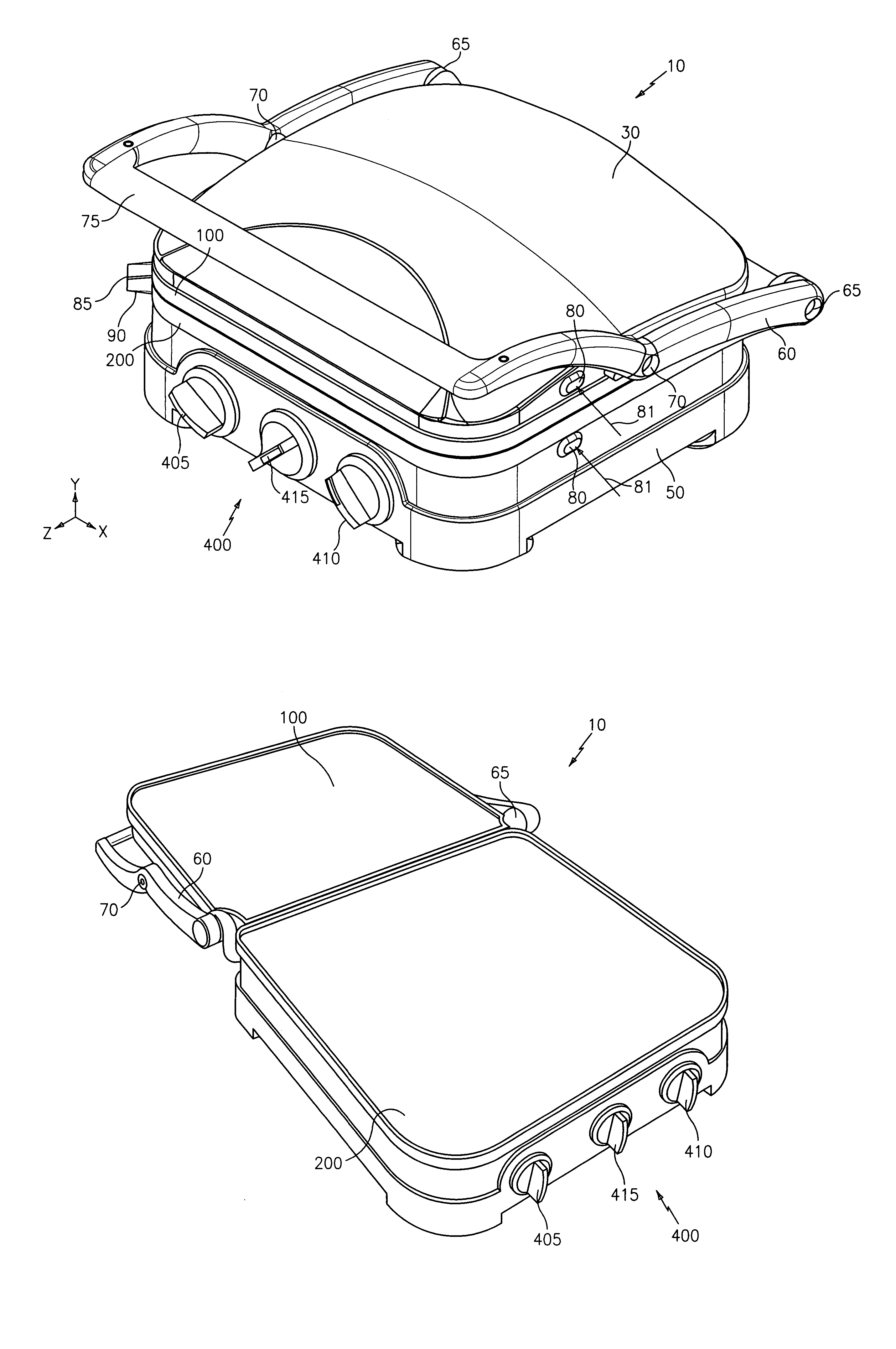
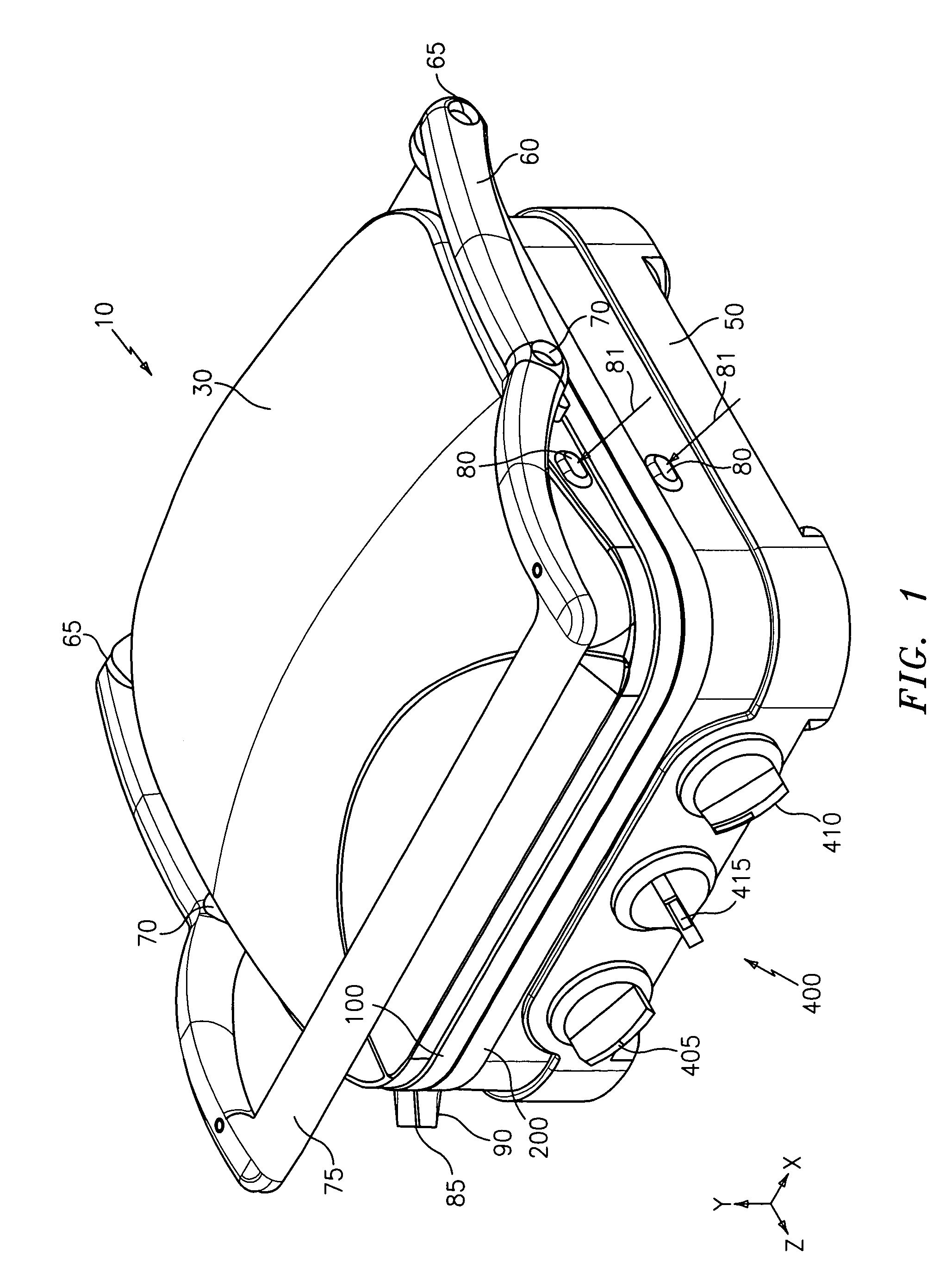
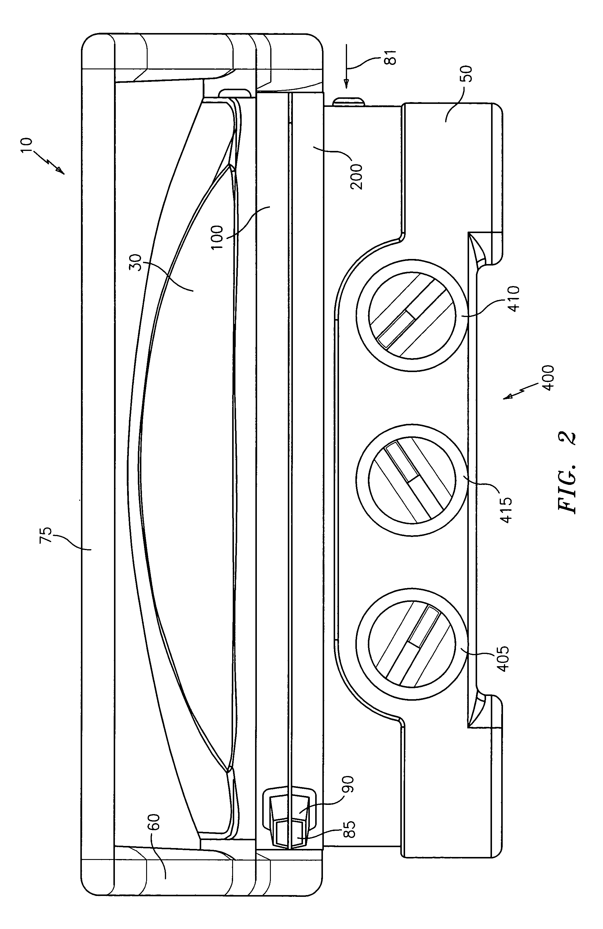
[0028]Referring to the drawings and in particular FIG. 1, there is shown a grill generally represented by reference numeral 10. Grill 10 has an upper housing 30, a lower housing 50 and a securing arm 60.

[0029]Securing arm 60 is connected to upper and lower housings 30, 50 to allow the housings to be selectively opened and closed. Preferably, securing arm 60 is pivotally connected to lower housing 50 at rear pivots 65. Securing arm 60 is preferably pivotally connected to upper housing 30 at center pivots 70. In one embodiment, rear pivots 65 are positioned at a rear portion of lower housing 50 and center pivots 70 are positioned at a center area of upper housing 30. By pivotally connecting the upper and lower housings 30, 50 at different areas along securing arm 60, the housings can be moved together for contact grilling so that the upper and lower housings are substantially parallel to each other.

[0030]Securing arm 60 preferably has a handle 75 for holding and manipulating the secur...


PUM


Abstract

A grill is provided that has an upper housing having a first heating plate removably connected thereto, a lower housing having a second heating plate removably connected thereto, and an arm FOR connecting to the upper housing at a first pivot point and connecting to the lower housing at a second pivot point.

Description

CROSS-REFERENCE TO RELATED APPLICATIONS[0001]This application claims priority to U.S. Provisional Application Ser. No. 60 / 483,850, filed on Jun. 30, 2003 and 60 / 515,824 filed Oct. 30, 2004, both of which are incorporated herein by reference in their entirety.BACKGROUND OF THE INVENTION[0002]1. Field of the Invention[0003]The present invention relates to a food heating device. More particularly, the present invention relates to a grill that cooks food items by grilling the food items.[0004]2. Description of the Related Art[0005]Grills, and in particular electric grills, are known. These devices are generally constructed with heating plates having a particular surface geometry for heating food placed thereon. The heating plates are typically secured to a housing and typically heated by an electrical resistance heater. However, these devices have the disadvantages of being limited to a fixed surface geometry for the heating plate and being difficult to clean since the heating plate is ...

Claims


Application Information

Patent Timeline
Patent Type & Authority Patents(United States)
IPC IPC(8): A47J37/06A47J37/08H05B3/06
CPCA47J37/0611
Inventor STEINBERG, HOWARD I.CARILLO, MICHELLEORENT, JILL KREUTZERGEIGER, AMYALJOBURI, MARIAPETROW, ERICARISINIT, AMY
Owner CONAIR CORP
Why Eureka
Try Eureka