Conductor optimized axial field rotary energy device

a rotary energy device and axial field technology, applied in the direction of windings, magnetic circuit rotating parts, magnetic circuit shape/form/construction, etc., can solve the problems of difficult manufacturing and relatively large size of motors

Active Publication Date: 2006-09-19
CORE MOTION
View PDF12 Cites 171 Cited by
  • Summary
  • Abstract
  • Description
  • Claims
  • Application Information

AI Technical Summary

Problems solved by technology

These motors were of relatively large size and difficult to manufacture.

Method used


Image

  • Conductor optimized axial field rotary energy device
  • Conductor optimized axial field rotary energy device
  • Conductor optimized axial field rotary energy device

Examples


Embodiment Construction

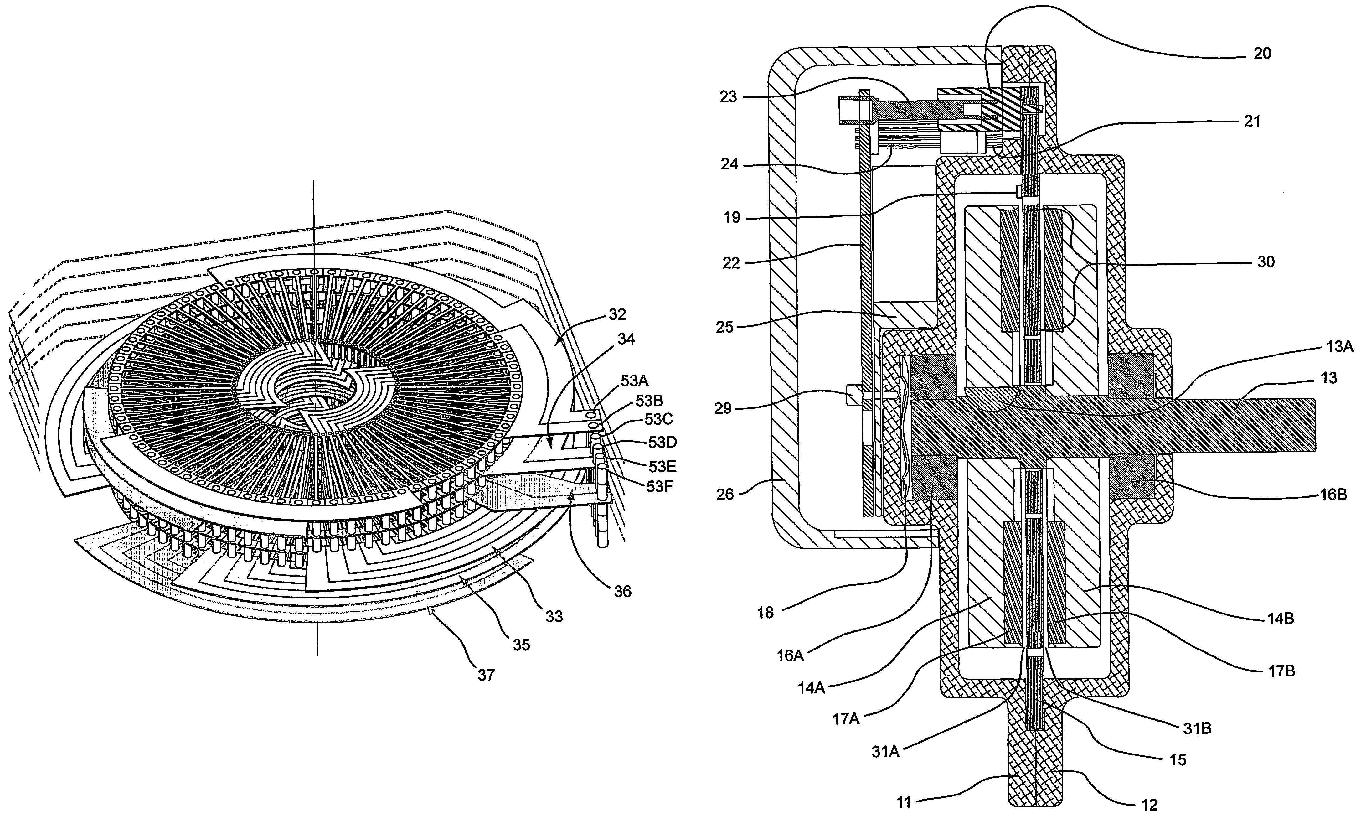
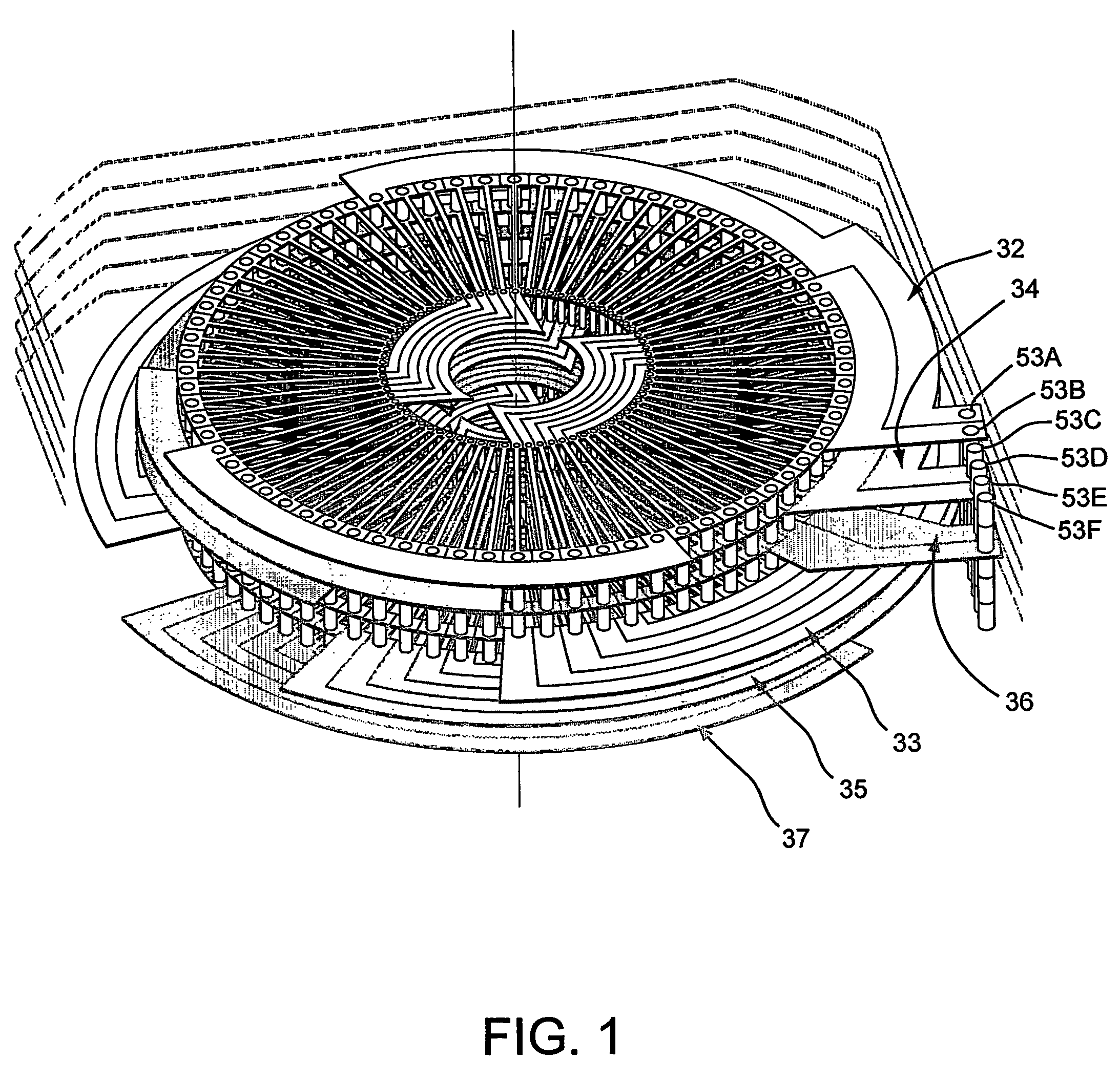
[0036]The present invention includes a stator formed by stacking a plurality of printed circuit boards (PCBs) containing a plurality of electrical circuits formed of a conductive material and supported by a nonconductive dielectric material. Overall, the invention is flat, relatively thin, and has a circular, square, or other shape suitable for the function of the device.

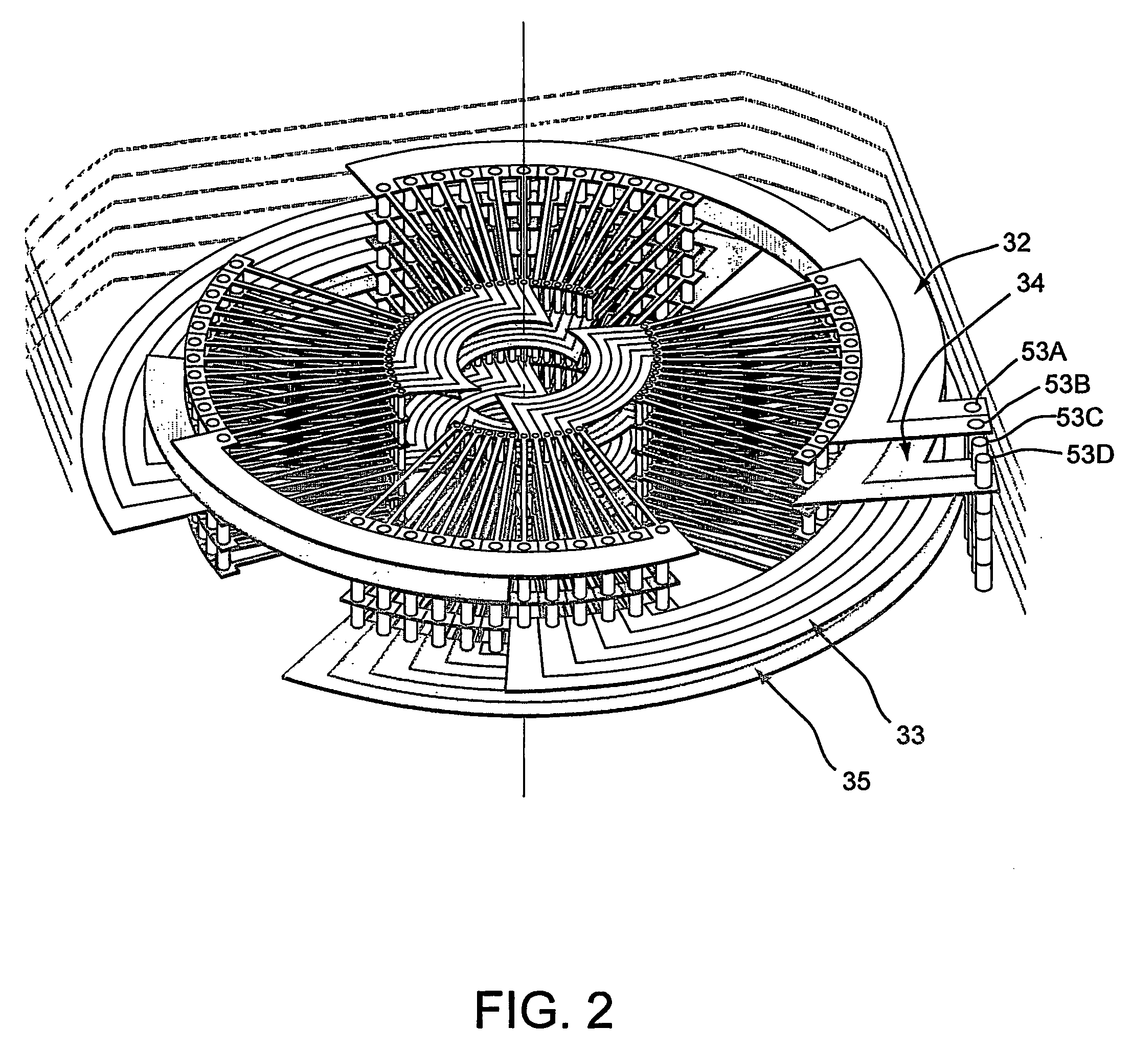
[0037]As a non-limiting example, FIG. 1 shows a three-dimensional view of one preferred embodiment of the invention comprised of six PCB layers arranged in a three phase electrical current configuration. The three phases are denoted herein as A, B and C. In FIG. 1, the axial scale has been exaggerated for clarity and the nonconductive material normally present for electrical insulation and mechanical support has been removed. FIG. 1 illustrates one of many possible arrangements whereby a phase A circuit, a phase B circuit, and phase C circuit intermesh and bypass one another. In FIG. 2, the phase C circuit has been ...


PUM


Abstract

The present invention provides an axial rotary energy device which is arranged in a multi-phase electric current configuration. The device includes a rotor having a plurality of permanent magnet poles secured thereto and further includes a stator formed by stacking a plurality of printed circuit board working conductor layers together with a plurality of printed circuit board connecting layers. The stator having at least one working conductor layer for each phase of the electric current and at least one connecting conductor layer associated with one working conducting layer. The working conductor layer and the connecting conductor layer each having radial conductors extending from an inner diameter through-hole to an outer diameter through-hole. A plurality of via conductors are provided for electrically connecting selected ones of the radial connectors of the connecting conductor layer to selected ones of the radial connectors of the working conductor layers through the through-holes.

Description

[0001]This application claims the benefit of provisional application Ser. No. 60 / 445,884, filed Feb. 7, 2003.BACKGROUND OF THE INVENTION[0002]The present invention relates to an optimized axial field rotary energy device which can be either used as a motor for converting electrical energy to motion or a generator for converting rotary motion to electrical energy. This invention includes a stator formed by stacking a plurality of printed circuit boards wherein the electrical components are arranged for maximum power and efficiency.[0003]Axial air gap brushless motors with layered disk stators are known, such as U.S. Pat. No. 5,789,841 to Wang. The stator winding in Wang utilizes wires interconnected in a wave or lap configuration. These motors were of relatively large size and difficult to manufacture.[0004]Further, axial field electric machines utilizing printed circuit board stators are also known such as shown in U.S. Pat. No. 6,411,002 to Smith et al.[0005]The present invention p...

Claims


Application Information

Patent Timeline
Patent Type & Authority Patents(United States)
IPC IPC(8): H02K3/00H02K1/22H02K3/04H02K1/27H02K3/26H02K3/28H02K3/50H02K5/16H02K11/04H02K21/24
CPCH02K11/0021H02K11/0073H02K21/24H02K3/26H02K3/28H02K3/47H02K3/50H02K1/2793H02K11/044H02K5/161H02K11/215H02K11/33H02K11/05H02K1/2795H02K16/02
Inventor JORE, LINCOLN M.JORE, MATTHEW B.
Owner CORE MOTION
Why Eureka
Try Eureka