Bipolar differential to single ended transfer circuit with gain boost
a transfer circuit and gain boost technology, applied in the field of differential to single-ended signal transfer circuit improvement, can solve the problems of affecting the affecting the ac performance and stability of the op amp, and imbalanced differential input stages, so as to increase the input impedance increase and reduce the input current of the transfer circuit.
- Summary
- Abstract
- Description
- Claims
- Application Information
AI Technical Summary
Benefits of technology
Problems solved by technology
Method used
Image
Examples
embodiment 500
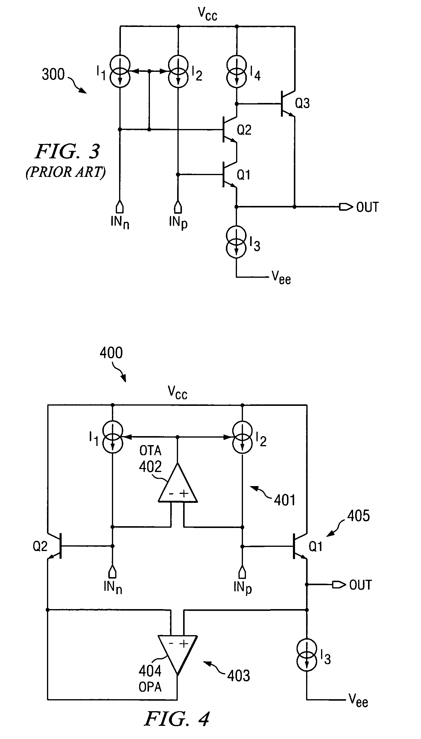
[0036]FIG. 5 depicts an alternative embodiment 500 of the differential to single-ended signal transfer circuit 400 (see FIG. 4). Like the transfer circuit 400, the transfer circuit 500 comprises the current mirror 401, the base current cancellation circuit 403, and the output buffer 405. The transfer circuit 500 further includes transistors Q3 and Q4, and a fourth current source I4. In the illustrated embodiment, the transistors Q3 and Q4 comprise respective PNP-type bipolar junction transistors (BJTs), and the current source I4 is implemented using the same bipolar IC technology as the BJTs Q1–Q4.
[0037]Specifically, the transistor Q3 and the current source I4 are configured to boost the current gain of the output buffer 405 including the transistor Q1. Further, because the addition of the transistor Q3 and the current source I4 may change the collector voltage of the transistor Q1, the diode-connected transistor Q4 is added to the transfer circuit 500 and configured to assure that ...
embodiment 600
[0038]FIG. 6 depicts an alternative embodiment 600 of the differential to single-ended signal transfer circuit 500 (see FIG. 5). Like the transfer circuit 500, the transfer circuit 600 comprises the current mirror 401, the base current cancellation circuit 403, the output buffer 405, the transistor Q3, and the current source I4. However, in place of the diode-connected transistor Q4 included in the transfer circuit 500, the transfer circuit 600 includes a third operational amplifier (OPA) 406 coupled between the respective collectors of the transistors Q1–Q2 as a voltage follower, thereby assuring that the collector voltage of the transistor Q2 is substantially equal to the collector voltage of the transistor Q1.
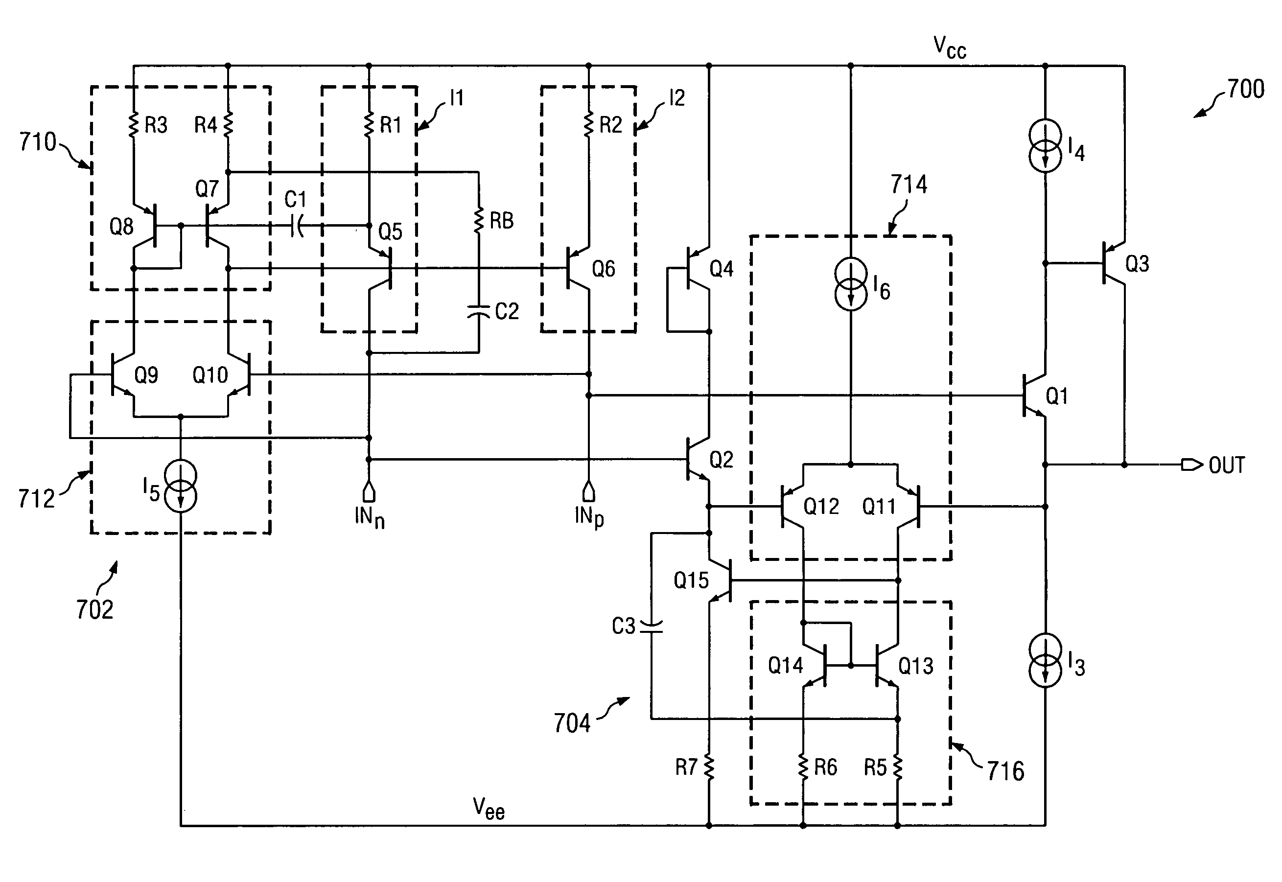
[0039]FIG. 7 depicts a detailed view 700 of the transfer circuit 500 (see FIG. 5). In the illustrated embodiment, a first circuit portion 702 corresponds to the OTA 402 (see FIGS. 4–5), and a second circuit portion 704 corresponds to the OPA 404 (see FIGS. 4–5). Specifically...
embodiment 800
[0042]FIG. 8 depicts an alternative embodiment 800 of the differential to single-ended signal transfer circuit 500 (see FIG. 5). Like the transfer circuit 500, the transfer circuit 800 comprises the OTA 402, the OPA 404, and the output buffer 405. The transfer circuit 800 further comprises a differential input stage 830, a folded cascode section 832, and a class-A output stage 820 coupled to the output buffer 405. The differential input stage 830 includes PNP-type BJTs Q1001 and Q1002, and a current source I1000. The folded cascode section 832 includes NPN-type BJTs Q1003 and Q1004 biased by a voltage source Vbias, and emitter degeneration resistors R1–R2 coupled between the transistors 1003–1004 and the supply voltage Vee, respectively. The class-A output stage 820 includes an emitter-follower transistor Q100, and a current source I101.
PUM
 Abstract
Description
Claims
Application Information
 - R&D
- Intellectual Property
- Life Sciences
- Materials
- Tech Scout
- Unparalleled Data Quality
- Higher Quality Content
- 60% Fewer Hallucinations
Browse by: Latest US Patents, China's latest patents, Technical Efficacy Thesaurus, Application Domain, Technology Topic, Popular Technical Reports.
© 2025 PatSnap. All rights reserved.Legal|Privacy policy|Modern Slavery Act Transparency Statement|Sitemap|About US| Contact US: help@patsnap.com


