Liquid crystal display device and electronic apparatus

a liquid crystal display and electronic device technology, applied in the direction of optics, polarising elements, instruments, etc., can solve the problems of increasing the cost or size of the device, reducing the luminance or contrast of the transmissive display area, and not achieving the enhancement

Active Publication Date: 2006-09-19
BOE TECH GRP CO LTD
View PDF14 Cites 2 Cited by
  • Summary
  • Abstract
  • Description
  • Claims
  • Application Information

AI Technical Summary

Benefits of technology

[0015]In a related art transflective liquid crystal display device, the optical path length is different between the reflective display area and the transmissive display area. Therefore, if the degree of polarization by the liquid crystal layer is adjusted to the reflective display area, the degree of polarization is inadequate in the transmissive display area and the luminance or contrast of the transmissive display area decreases. The inventor of the present invention found that it is preferable to control the twist angle of the liquid crystal layer and the product Δn·d (retardation value) of birefringence difference Δn of the liquid crystal and thickness d of the liquid crystal layer within the above range in order to obtain a structure of liquid crystal layer that can maximize the luminance of the transmissive display area without lowering the quality of display in the reflective display area. In the liquid crystal display device of an aspect of the present invention, by determining the twist angle and Δn·d (retardation value) of transmissive display area and the reflective display area within the above range, it is possible to achieve both superior luminance in the transmissive display area and superior quality of display in the reflective display area at a usable drive voltage.
[0016]In an aspect of the present invention, the liquid crystal cell may have an adjusting layer to make the thickness of the liquid crystal layer in the reflective display area smaller than that in the transmissive display area. In the transflective liquid crystal display device, transmissive display light passes through the liquid crystal layer only once and then it is output. Reflective display light passes through the liquid crystal layer twice. Therefore, it is difficult to optimize the retardation Δn·d in both the transmissive display light and the reflective display light. By providing an adjusting layer to make the thickness of the liquid crystal layer different between the reflective display area and the transmissive display area, it is possible to optimize the retardation Δn·d in both the transmissive display light and the reflective display light, and to achieve bright reflective display and transmissive display.
[0017]Next, the liquid crystal display device of an aspect of the present invention can be used as a display unit of an electronic apparatus, such as a mobile phone and a mobile computer. Such an electronic apparatus has a reflective display mode and a transmissive display mode. It can perform display with superior viewing-angle characteristics in each mode. Also in the reflective display mode, display that is bright, with high contrast, and with less dependence on the viewing angle is achieved.

Problems solved by technology

However, in the reflective display mode, such an enhancement is not attained because the optical anisotropic element is disposed at the rear of the transflective layer as viewed from the observer.
If the liquid crystal display device is applied to an electronic apparatus used often in the reflective display mode, the provided optical anisotropic element does not fulfill its function.
In addition, providing a useless element causes an increase in cost or size of the device.

Method used


Image

  • Liquid crystal display device and electronic apparatus
  • Liquid crystal display device and electronic apparatus
  • Liquid crystal display device and electronic apparatus

Examples


first exemplary embodiment

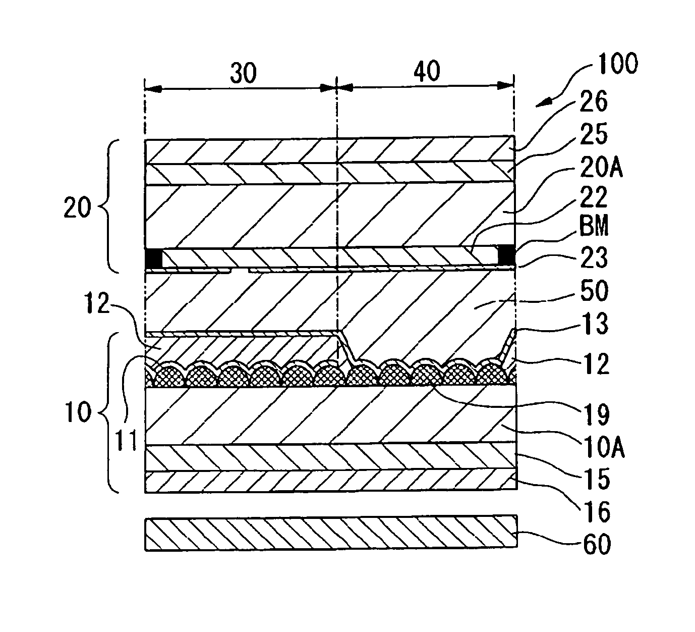
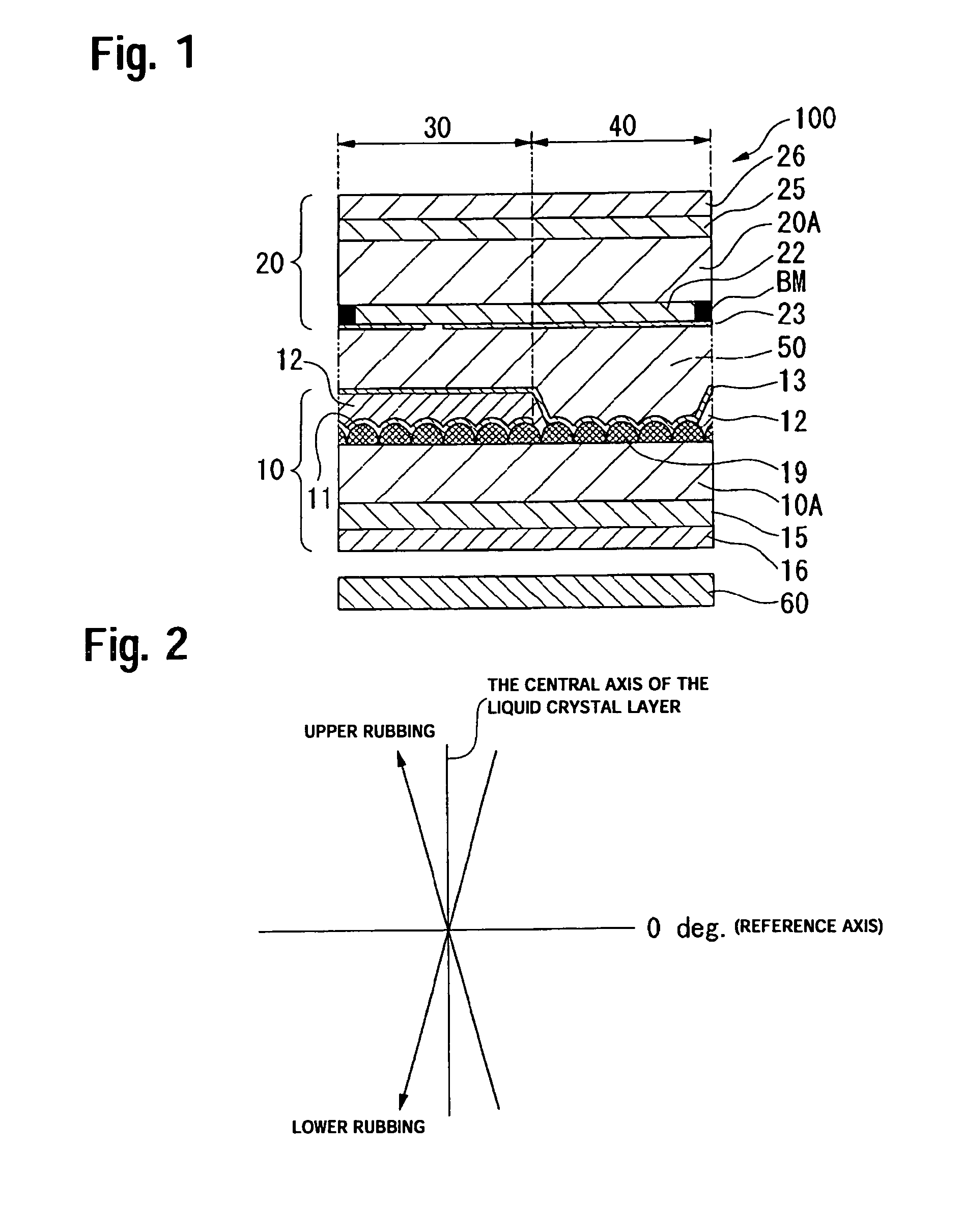
[0031]FIG. 1 a partial sectioned schematic showing a pixel of a liquid crystal display device having the structure according to an aspect of the present invention. The liquid crystal display device 100 shown in this figure is an active-matrix transflective liquid crystal display device including a liquid crystal layer 50 disposed between an array substrate 10 and an opposite substrate 20 facing each other. A backlight 60 is provided on the outer side of the array substrate 10. A reflective display area 30 and a transmissive display area 40 are provided in one pixel. The liquid crystal display device 100 of this exemplary embodiment has a display surface on the upper side in the drawing (on the outer side of the opposite substrate 20). An observer who views the display is disposed on the upper side in the drawing.

[0032]With respect to the array substrate 10 shown in FIG. 1, on the liquid crystal layer 50 side of the lower substrate 10A, a rough resin layer 19 for scattering is formed...

examples

[0042]In order to confirm the advantageous effect of the first exemplary embodiment, with respect to the following example and comparative examples, the display characteristics were evaluated.

second exemplary embodiment

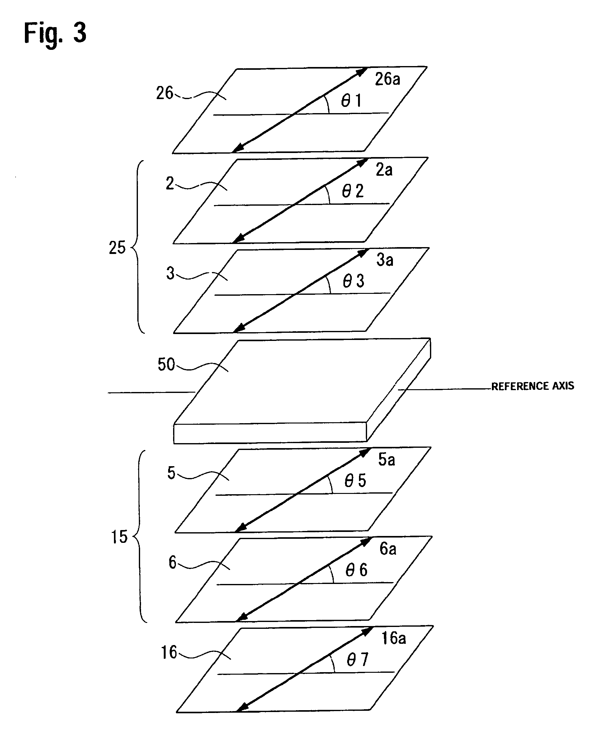
[0053]A liquid crystal display device of a second exemplary embodiment will now be described with reference to FIG. 10. FIG. 10 is comparable to FIG. 3 of the first exemplary embodiment.

[0054]The liquid crystal display device of the second exemplary embodiment is an active-matrix transflective liquid crystal display device as in the first exemplary embodiment. However, as shown in FIG. 10, retardation plates and polarizers provided to the opposed substrates with the liquid crystal layer 50 therebetween are different from those of the first exemplary embodiment. Except for retardation plates and polarizers, since the second exemplary embodiment is the same as the first exemplary embodiment, the description thereof will be omitted.

[0055]In this exemplary embodiment, on the backlight side (the outer side of the lower substrate), a retardation plate 115 and a linear polarizer 116 are disposed as an elliptical polarizer. On the observer side (the outer side of the upper substrate), a ret...


PUM

PropertyMeasurementUnit
twist angleaaaaaaaaaa
angleaaaaaaaaaa

Abstract

The invention provides a transflective liquid crystal display device in which display is bright, with high contrast, and with less dependence on the viewing angle in the transmissive display mode. A liquid crystal display device includes a liquid crystal cell, the liquid crystal cell including an upper substrate, a lower substrate, a liquid crystal layer between the upper and lower substrates, and a transflective layer on the inner surface of the lower substrate. The liquid crystal display device further includes a first elliptical polarizer elliptical polarized light from the upper substrate being incident on the liquid crystal layer; and a second elliptical polarizer, elliptical polarized light from the lower substrate being incident on the liquid crystal layer. Only the first elliptical polarizer has a liquid crystal film in which a hybrid alignment is fixed.

Description

BACKGROUND OF THE INVENTION[0001]1. Field of Invention[0002]The present invention relates to a transflective liquid crystal display device enabling both a reflective mode and a transmissive mode, and an electronic apparatus including the same.[0003]2. Description of Related Art[0004]A transflective liquid crystal display device combining a reflective display mode with a transmissive display mode consumes lower amounts of power and performs clear display regardless of ambient brightness by switching to either a reflective display mode or a transmissive display mode according to ambient brightness.[0005]A related art transflective liquid crystal display device has a structure in which a liquid crystal layer is disposed between an upper substrate and a lower substrate each having a circular polarizer. It has a reflective film formed of metal, such as aluminum, on the inner side of the lower substrate, the film having a slit to transmit light. This reflective film functions as a transfl...

Claims


Application Information

Patent Timeline
Patent Type & Authority Patents(United States)
IPC IPC(8): G02F1/1335G02F1/13G02B5/30G02F1/13363
CPCG02F1/133528G02F1/133555G02F1/13363G02F2413/105G02F2001/133638G02F2202/40G02F2413/04G02F2001/133633G02F1/133633G02F1/133638G02F1/1335
Inventor MATSUSHIMA, TOSHIHARU
Owner BOE TECH GRP CO LTD
Why Eureka
Try Eureka