
Setting method and setting apparatus for operation path for articulated robot

Inactive Publication Date: 2006-09-19
HONDA MOTOR CO LTD
View PDF26 Cites 54 Cited by
  • Summary
  • Abstract
  • Description
  • Claims
  • Application Information

AI Technical Summary

Benefits of technology

[0016]In consideration of the above problems, it is an object of the present invention to provide a setting method and a setting apparatus for an operation path for an articulated robot, in which steps for determining the path are automatically performed, and teaching data can be prepared in a short period of time without requiring any skill, when off-line teaching is performed for a withdrawing path to make no interference with a workpiece, in a narrow-area operation path for withdrawing an end effector from an operation point on the workpiece, of operation paths for an articulated robot.
[0017]Another object of the present invention is to provide a setting method and a setting apparatus for an operation path for an articulated robot, in which a wide-area operation path for making movement between operation points or between withdrawing positions can be set automatically and efficiently without performing any complicated calculation which may be affected by the shape of a workpiece and / or an obstacle.
[0018]Still another object of the present invention is to provide a setting method and a setting apparatus for an operation path for an articulated robot, in which a narrow-area operation path and a wide-area operation path can be set automatically and efficiently.
[0020]Accordingly, the steps for determining the path are automatically performed, and teaching data can be prepared in a short period of time without requiring any skill, when off-line teaching is performed for a withdrawing path to make no interference with a workpiece, in a narrow-area operation path for withdrawing an end effector from an operation point on the workpiece.
[0029]Accordingly, a wide-area operation path for making movement between operation points or between withdrawing positions can be set automatically and efficiently without performing any complicated calculation which may be affected by the shape of a workpiece or an obstacle.
[0037]Accordingly, it is possible to set the narrow-area operation path and the wide-area operation path automatically and efficiently.

Problems solved by technology

Accordingly, the operation becomes inefficient.
Therefore, it is unnecessary to stop the production line during the preparation of the teaching data.
When various peripheral structures exist or when the workpiece is of a complicated shape, it is difficult to set an operation path to avoid such obstacles.
More specifically, the round-robin method, in which the interference is investigated as to all postures of the articulated robot, is not practical, because the amount of calculation is enormous.
Further, according to the stochastic technique using random numbers, the convergence of solution is not assured and the calculation has no reproducibility.
For this reason, the verifying operation is complex, and the operation path is complicated.
Even if the operation path is proper, it is also impossible to verify whether the articulated robot can actually operate on the operation path from a viewpoint of operation ranges of respective axes.
However, in this technique, the operation path cannot be set automatically, because the teaching is performed while operating the actual machine at the production site.
However, the manual operation needs a long period of time to extract a non-interference area in which the robot does not interfere with the workpiece and other equipments.
It is inevitable to cause any oversight and / or any omission for the extraction point.
As described above, when the posture of the robot is determined by means of the off-line teaching, the operation required therefor is not necessarily easy.
Especially, it is difficult to retrieve a path for retracting a gun unit from a welding point so that it may not interfere with a workpiece, on a monitor screen, when the workpiece is of a complicated three-dimensional shape.
It takes a long period of time to perform the teaching.

Method used


Image

  • Setting method and setting apparatus for operation path for articulated robot
  • Setting method and setting apparatus for operation path for articulated robot
  • Setting method and setting apparatus for operation path for articulated robot

Examples


Embodiment Construction

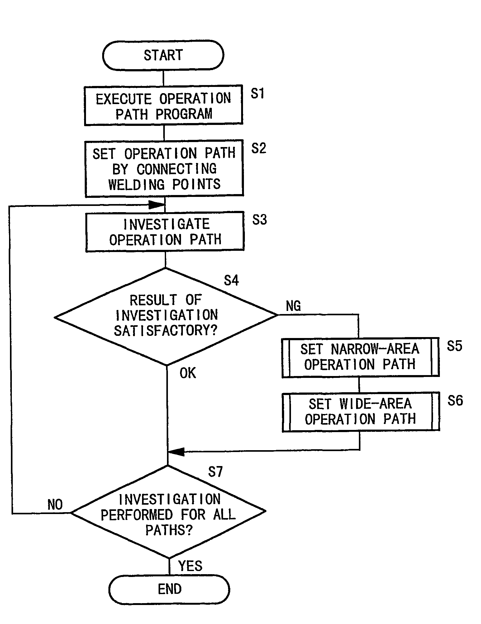
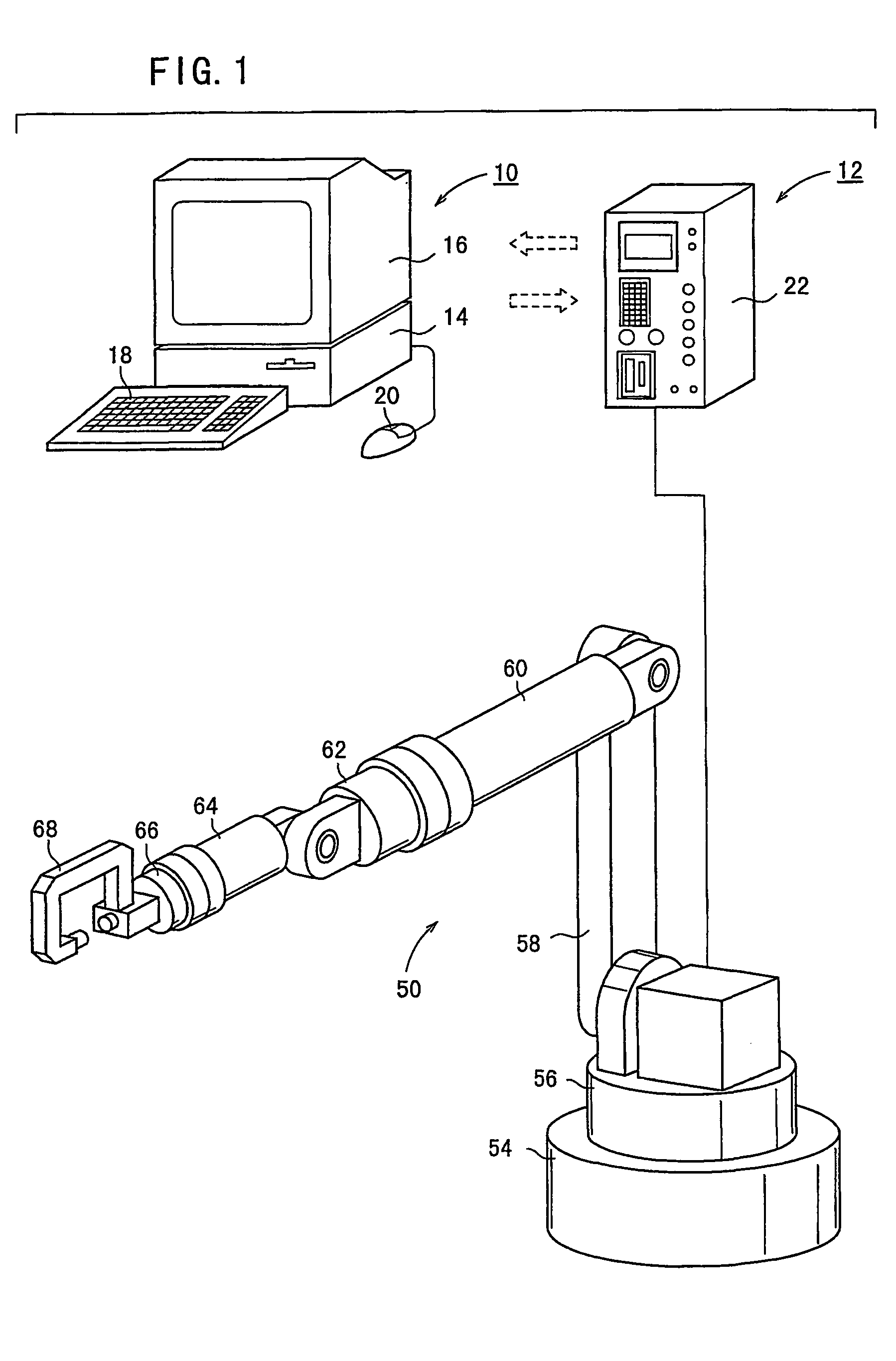
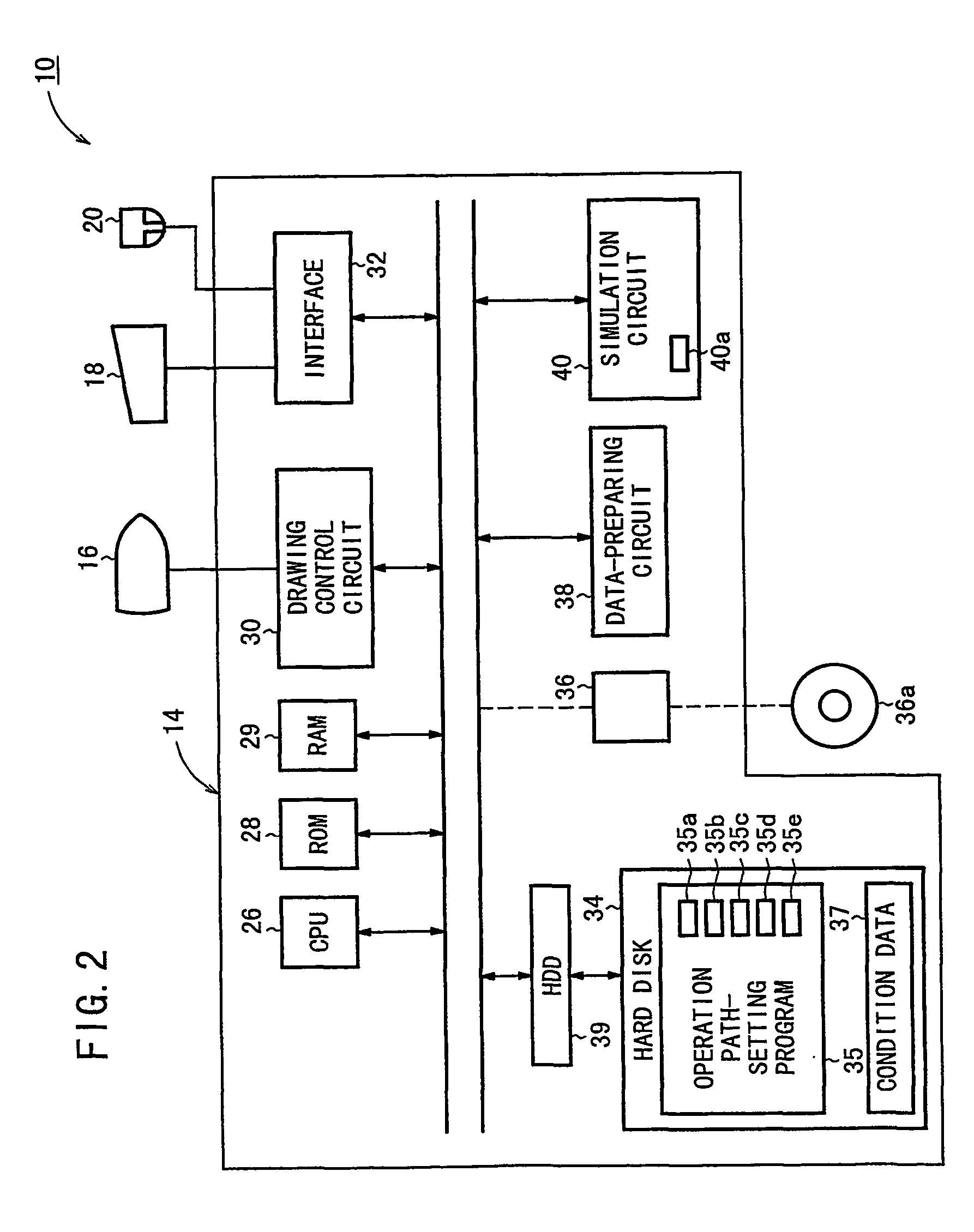
[0069]Illustrative embodiments of the setting method and the setting apparatus for the operation path for the articulated robot according to the present invention will be explained below with reference to FIGS. 1 to 21.

[0070]Basically, in the setting method and the setting apparatus for the operation path for the articulated robot according to the embodiment of the present invention, the operation path is set while extracting the portion in which the workpiece exists to investigate the interference in the internal space surrounded by the gun unit during the narrow-area operation in which the end effector provided at the forward end of the articulated robot is withdrawn from the operation point on the workpiece. During the wide-area operation for making movement between the withdrawing positions, the operation path is set to move to the arrival point while avoiding the obstacle by operating while combining the template operations for making movement from the start point by the prescr...


PUM

PropertyMeasurementUnit
Gravityaaaaaaaaaa
Distanceaaaaaaaaaa

Abstract

A temporary operation path is set by connecting a plurality of welding points in a virtual space generated by a computer to investigate whether an end effector can be operated along the temporary operation path. If the operation cannot be operated, a path to avoid interference with a workpiece is set automatically while extracting a portion in which the workpiece exists in the internal space surrounded by the end effector in order to set a narrow-area operation path for withdrawing the end effector from a welding point. Next, in order to set a wide-area operation path for making movement between withdrawing points, a template operation is applied, in which the end effector is moved by a prescribed distance in a prescribed direction.

Description

[0001]This application is the national phase under 35 U.S.C. § 371 of PCT International Application No. PCT / JP01 / 10202 which has an International filing date of Nov. 22, 2001, which designated the United States of America.[0002]1. Technical Field[0003]The present invention relates to a setting method and a setting apparatus for an operation path for an articulated robot. Specifically, the present invention relates to a setting method and a setting apparatus for an operation path for an articulated robot, for setting the path for operating an end effector provided at a forward end of the articulated robot, between predetermined operation points.[0004]2. Background Art[0005]Conventionally, if an articulated robot installed for a production line is directly operated to perform the teaching of the operation posture, an operator skilled in the operation of the articulated robot should perform the operation at the working site of the production line. Accordingly, the operation becomes ine...

Claims


Application Information

Patent Timeline
IPC IPC(8): G06F19/00B23K11/11B23K11/24B25J9/16B25J9/18B25J9/22G05B19/18G05B19/4061G05B19/42
CPCB23K11/11B25J9/1666G05B2219/45104G05B2219/39094
Inventor SHIBATA, KAORUNAKAJIMA, RYOKANEKO, MASAKATSU
Owner HONDA MOTOR CO LTD
Learn More