Speech coding apparatus and speech decoding apparatus

a speech coding and speech technology, applied in the field of speech coding apparatus and speech decoding apparatus, can solve the problems of complex processing, unvoiced consonants and background noises, and sound quality greatly deteriorating mainly on voiced speeches, and achieve excellent sound quality

Inactive Publication Date: 2006-09-19
III HLDG 12 LLC
View PDF7 Cites 8 Cited by
  • Summary
  • Abstract
  • Description
  • Claims
  • Application Information

AI Technical Summary

Benefits of technology

[0014]An object of the present invention is to provide a speech coding apparatus and a speech decoding apparatus capable of effectively coding any of voiced speeches, unvoiced speeches and background noises and obtaining speeches with excellent qualities with a small amount of information and a small amount of computations.
[0016]Based on the foregoing consideration, the inventors found out that the perception is improved by identifying a speech as voiced sound segment, or unvoiced sound segment and background noise segment by recognizing a distance of pulse positions, and based on the identification result, applying respective pulse sequences appropriate for the voiced sound segment, and the unvoiced and background noise segments, to achieve the present invention.
[0018]Accordingly, without using particular voiced / unvoiced speech judgement algorithm, it is possible to automatically select an excitation most suitable for the localized characteristics in input signals, effectively code any of voiced speeches, unvoiced speeches and background noises, and obtain synthesized speeches with excellent sound qualities with a small amount of information and a small amount of computations.

Problems solved by technology

However, an application of algebraic codebook with a small number of pulses to coding at lower bit rates introduces a phenomenon that sound qualities greatly deteriorate mainly on unvoiced consonants and background noises.
On the other hand, an application of excitation with a large number of pulses such as random number sequence to coding at lower bit rates introduces a phenomenon that sound qualities greatly deteriorate mainly on voiced speeches.
However, the method has the complicated processing and sometimes generates an allophone caused by a judgement error on a speech signal.

Method used


Image

  • Speech coding apparatus and speech decoding apparatus
  • Speech coding apparatus and speech decoding apparatus
  • Speech coding apparatus and speech decoding apparatus

Examples


first embodiment

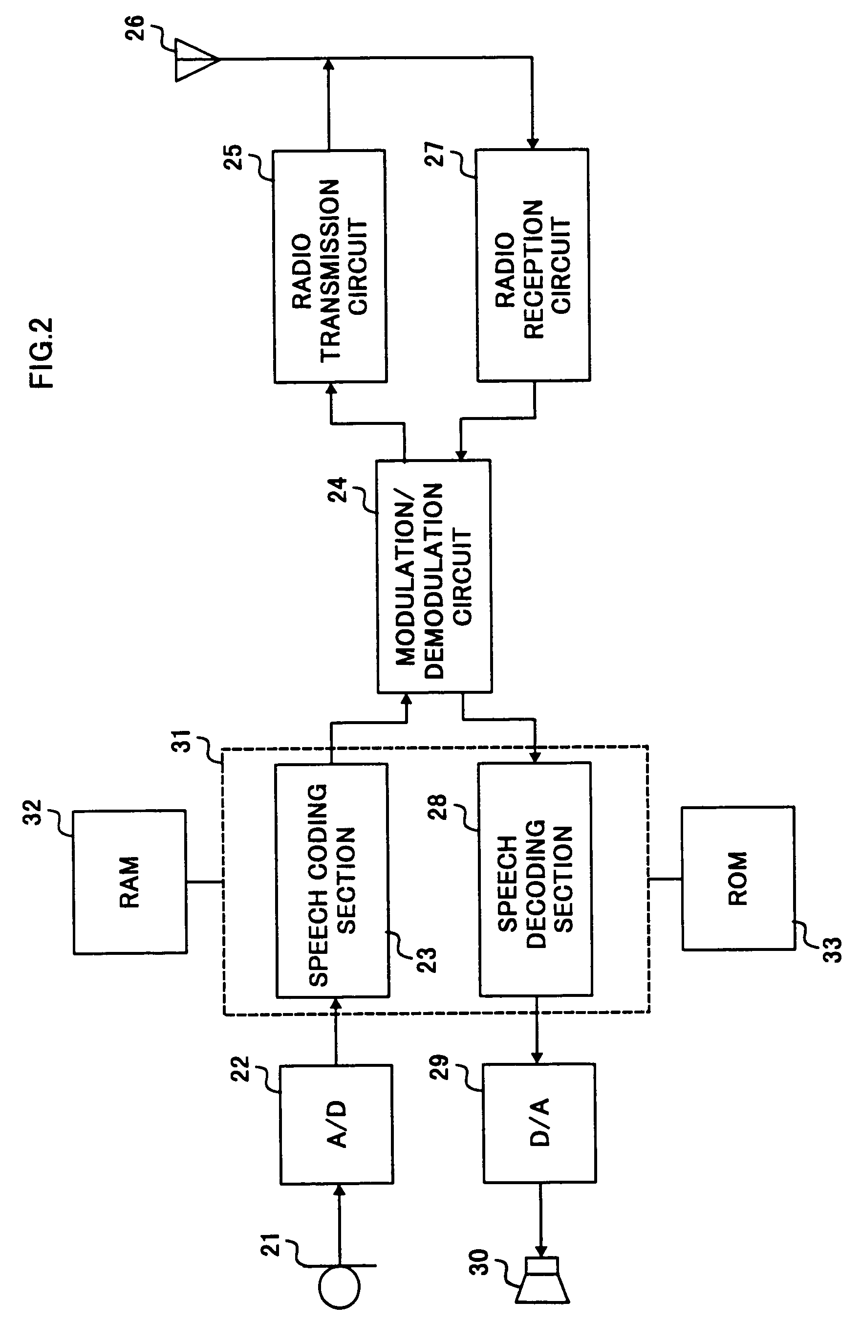
[0032]FIG. 2 is a block diagram illustrating a configuration of a radio communication apparatus having a speech coding / decoding apparatus according to the first embodiment to the third embodiment of the present invention.

[0033]In this radio communication apparatus, at a transmitting side, a speech is converted into electric analogue signals at speech input device 21 such as a microphone and output to A / D converter 22. The analogue speech signals are converted into digital speech signals at A / D converter 22 and output to speech coding section 23. Speech coding section 23 executes speech coding processing on the digital speech signals and outputs the coded data to modulation / demodulation circuit 24. Modulation / demodulation circuit 24 executes digital modulation on the coded speech signals to output to radio transmission circuit 25. Radio transmission circuit 25 executes the predetermined radio transmission processing on the modulated signals. The signals are transmitted via antenna 26...

second embodiment

[0071]This embodiment will describes about the case where a gain calculating section obtains decoded LPC from LPC analyzing section 42 and performs a voiced / unvoiced judgement using the obtained LPC.

[0072]FIG. 8 is a block diagram illustrating a stochastic codebook in the speech coding apparatus / speech decoding apparatus according to the second embodiment of the present invention. The configurations of the speech coding apparatus and the speech decoding apparatus with the stochastic code book are the same as the first embodiment (FIG. 3 and FIG. 4).

[0073]The stochastic codebook has first codebook 71 and second codebook 72, and first codebook 71 and second codebook 72 respectively have two subcodebooks 71a, 71b and subcodebooks 72a, 72b. The stochastic codebook further has gain calculating section 73 which calculates a gain for outputs from subcodebooks 71b and 72b using pulse positions in subcodebooks 71a and 72a.

[0074]Subcodebooks 71a and 72a are mainly used in the case where a sp...

third embodiment

[0094]This embodiment will describe about the case of switching an excitation vector to acquire from a subcodebook corresponding to a distance of pulse intervals.

[0095]FIG. 9 is a block diagram illustrating a stochastic codebook in the speech coding apparatus / speech decoding apparatus according to the third embodiment of the present invention. The configurations of the speech coding apparatus and the speech decoding apparatus with the stochastic code book are the same as the first embodiment (FIG. 3 and FIG. 4).

[0096]The stochastic codebook has first codebook 91 and second codebook 92, and first codebook 91 and second codebook 92 respectively have two subcodebooks 91a, 91b and subcodebooks 92a, 92b. The stochastic codebook further has excitation switching instructing section 93 which executes switching between outputs from subcodebooks 91b and 92b corresponding to a pulse position in subcodebooks 91a and 92a.

[0097]Subcodebooks 91a and 92a are mainly used in the case where a speech ...


PUM


Abstract

First codebook 61 and second codebook 62 respectively have two subcodebooks, and in respective codebooks, addition sections 66 and 67 obtain respective excitation vectors by adding sub-excitation vectors fetched from respective two subcodebooks. Addition section 68 obtains an excitation sample by adding those excitation vectors. According to the aforementioned constitution, it is possible to store sub-excitation vectors with different characteristics in respective sub-codebooks. Therefore, it is possible to correspond to input signals with various characteristics, and achieve excellent sound qualities at the time of decoding.

Description

TECHNICAL FIELD[0001]The present invention relates to a speech coding apparatus and a speech decoding apparatus using speech coding algorithm at low bit rates, used in digital communications such as a portable telephone.BACKGROUND ART[0002]Speech compression coding methods at low bit rates have been required in order to accept an increase of subscribers in digital mobile communications such as a portable telephone, and the researches and developments have been proceeded by many research institutions. In Japan, applied coding systems as a standard system in portable telephones are VSELP at a bit rate of 11.2 kbps developed by Motorola and PSI-CELP at a bit rate of 5.6 kbps developed by NTT Mobile Communications Network, INC., and portable telephones with these system are produced.[0003]In addition, internationally, the ITU-T selected CS-ACELP, which was co-developed by Nippon Telegraph and Telephone Corporation and France Telecom, as an international standard speech coding system G.7...

Claims


Application Information

Patent Timeline
Patent Type & Authority Patents(United States)
IPC IPC(8): G10L19/12G10L19/04G10L19/038G10L19/083G10L19/20G10L19/22G10L25/93H03M7/30
CPCG10L19/12G10L2019/0005G10L2019/0014
Inventor MORII, TOSHIYUKIYASUNAGA, KAZUTOSHI
Owner III HLDG 12 LLC
Why Eureka
Try Eureka