
Fastening device

a technology of fastening device and cradle, which is applied in the direction of lighting support device, washstand, instruments, etc., can solve the problems of not being able to attach a holster or carrier to a person dressed in such attire, too often falling off, and being sat on, etc., to achieve the effect of convenient detachability

Inactive Publication Date: 2006-09-26
SHANNON EUGENE E +1
View PDF18 Cites 46 Cited by
  • Summary
  • Abstract
  • Description
  • Claims
  • Application Information

AI Technical Summary

Benefits of technology

The solution effectively secures small electronic devices and drink containers, preventing them from falling or being lost, while allowing easy detachment and maintaining an upright position during movement or changes in orientation.

Problems solved by technology

There is a disadvantage that such cellular telephones and other electronic devices are small and too often become misplaced, sat on, or knocked onto the ground or into the water, especially when the telephone or other device is located on a patio, poolside or on a boat and is not carried in a holster or other carrier attached to a person' attire.
There is no way to attach a holster or carrier to a person dressed in such attire.
These existing holsters or cradles does not work in locations and situations such as described in the previous paragraph.
However, too often, such a cup or glass holders are not available or not located in a position that is convenient for a user and they then place these items on various flat surfaces from which they are too easily knocked over, or slide when the boat is in motion.
In addition, even when a glass, bottle or can is positioned in such a cup or glass holder, if the container is full and the boat pitches off vertical in a swell from another boat or due to rough water, the contents therein spills because the container does not remain in a vertical position.

Method used


Image

  • Fastening device
  • Fastening device
  • Fastening device

Examples


Embodiment Construction

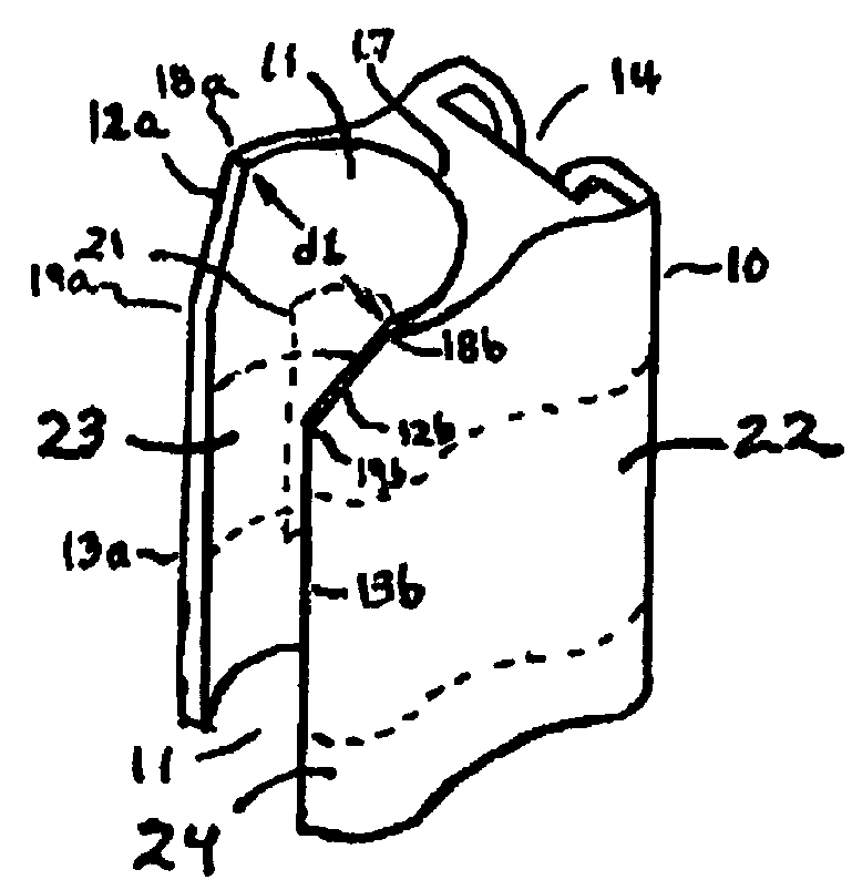
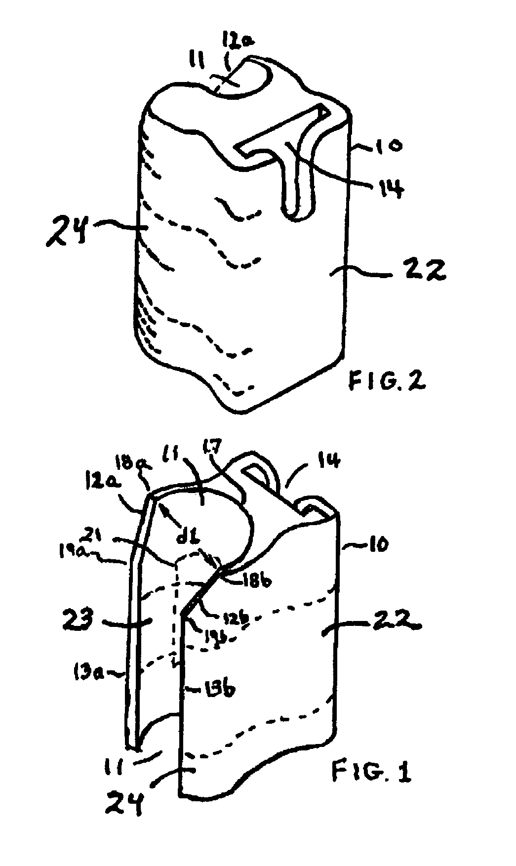
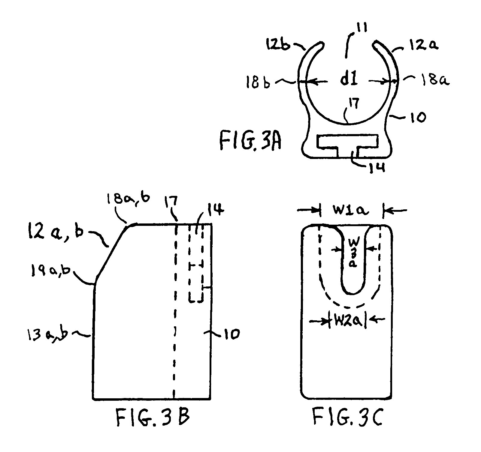
[0014]There are dashed lines shown on the outer surface of the fastening device 10 in FIGS. 1 and 2. These dashed lines form no specific part of the fastening device 10 and are only meant to show contours of the surface of device 10. Novel fastening device 10 is quickly and easily attached or removed from a pole 15 (FIGS. 5A and 5B) without the use of tools. Other items such as, but not limited to, cup holders and electronic devices are quickly and conveniently attached to and detached from fastening device 10 as shown in FIGS. 5A and 5B. In FIGS. 5A and 5B a hand-held radio 20 is shown attached to device 10 which in turn is attached to a pole 15. Pole 15 preferably has a circular cross-section.

[0015]FIG. 1 shows a front orthogonal view of novel fastening device 10. Device 10 is molded or otherwise fabricated from a plastic material, such as DELRIN plastic or nylon, which is strong, tough and will not easily break, yet has a sufficient amount of flexibility. Device 10 may be of any ...


PUM


Abstract

A fastening device is disclosed for attachment to a pole without the need for tools and without the need for excessive force to mount or remove the device from the pole. The device has an interior channel that is open along a side of the fastening device. The opening in the channel along the side of the device is defined by first edges that are uniformly spaced apart and contiguous second edges that are angled away from each other, starting with the spacing of the first edges, until their spacing is equal to the diameter of the pole. To mount the fastening device to the pole its top edge with the widest spacing of the second edges are placed against the pole and pushed on to the pole for a short distance before rotating the bottom of the fastening device on to the pole. This attachment sequence distributes the mounting force timewise making it easier to attach or remove the fastening device to or from the pole.

Description

FIELD OF THE INVENTION[0001]This invention relates to a device for attaching and securing an implement or instrument, such as a cellular telephone to a pole.BACKGROUND OF THE INVENTION[0002]Cellular telephones and other small electronic devices such as portable radios are commonly used all over the world. There is a disadvantage that such cellular telephones and other electronic devices are small and too often become misplaced, sat on, or knocked onto the ground or into the water, especially when the telephone or other device is located on a patio, poolside or on a boat and is not carried in a holster or other carrier attached to a person' attire. This is too often the case when people are wearing bathing suits and are outdoors on a patio, poolside or on a boat. There is no way to attach a holster or carrier to a person dressed in such attire. The cellular telephones or other devices can only be placed on tables, chairs, lounges, shelves or other places where they can be sat on, cov...

Claims


Application Information

Patent Timeline
Patent Type & Authority Patents(United States)
IPC IPC(8): G09F7/18
CPCF16M13/022H04M1/04F16M11/041F16M13/00F16M13/02A45F5/02A45F2005/026A45F2200/0516
Inventor SHANNON, EUGENE E.SHANNON, PAUL
Owner SHANNON EUGENE E
Learn More