

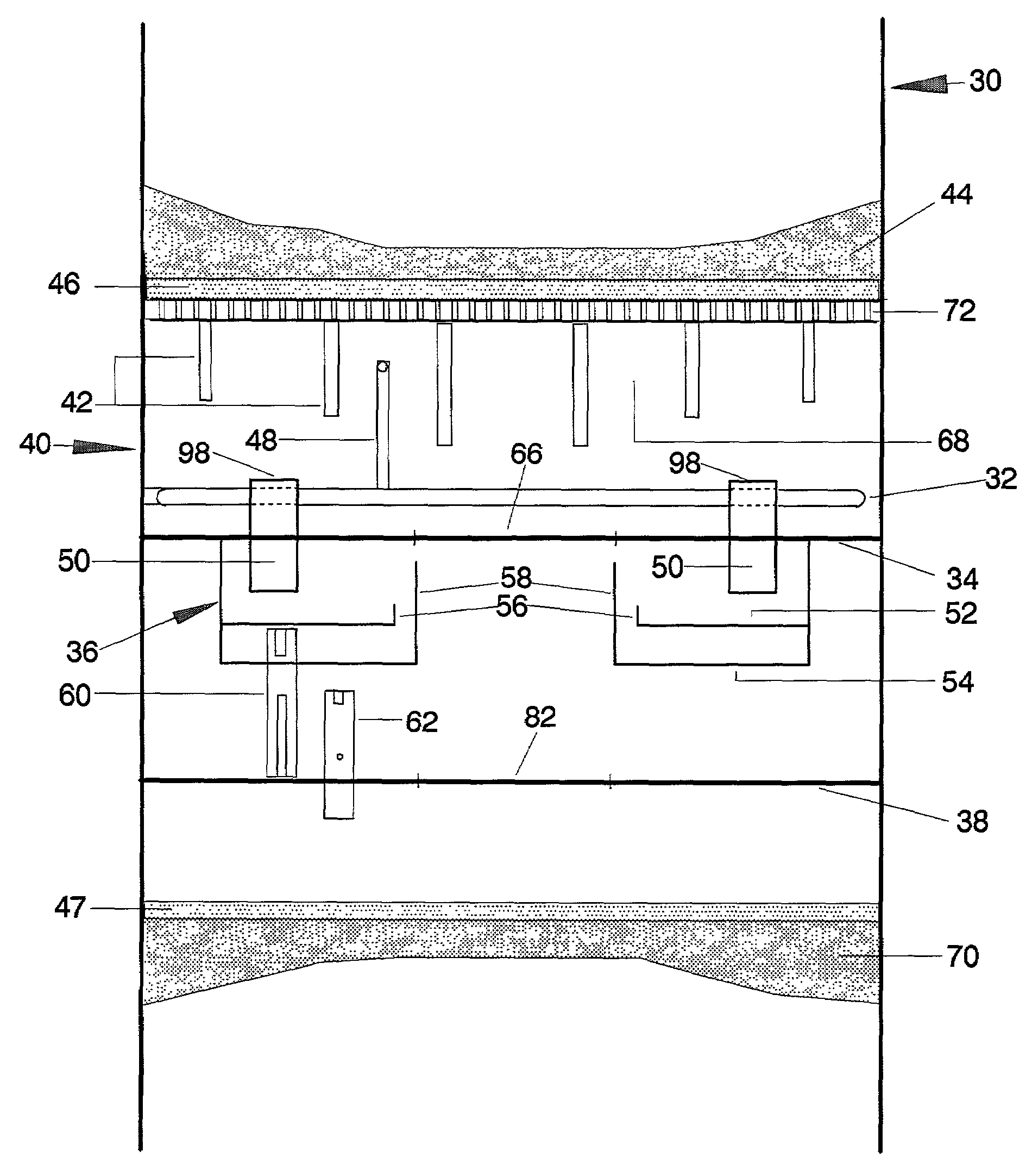
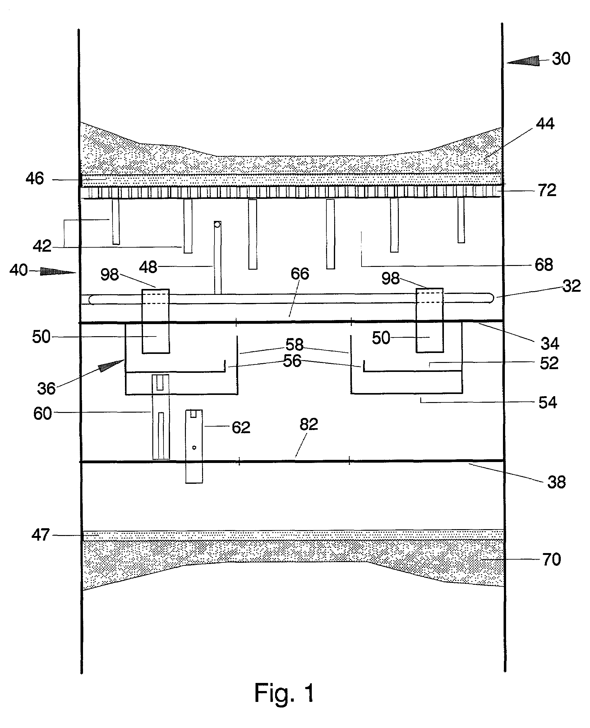
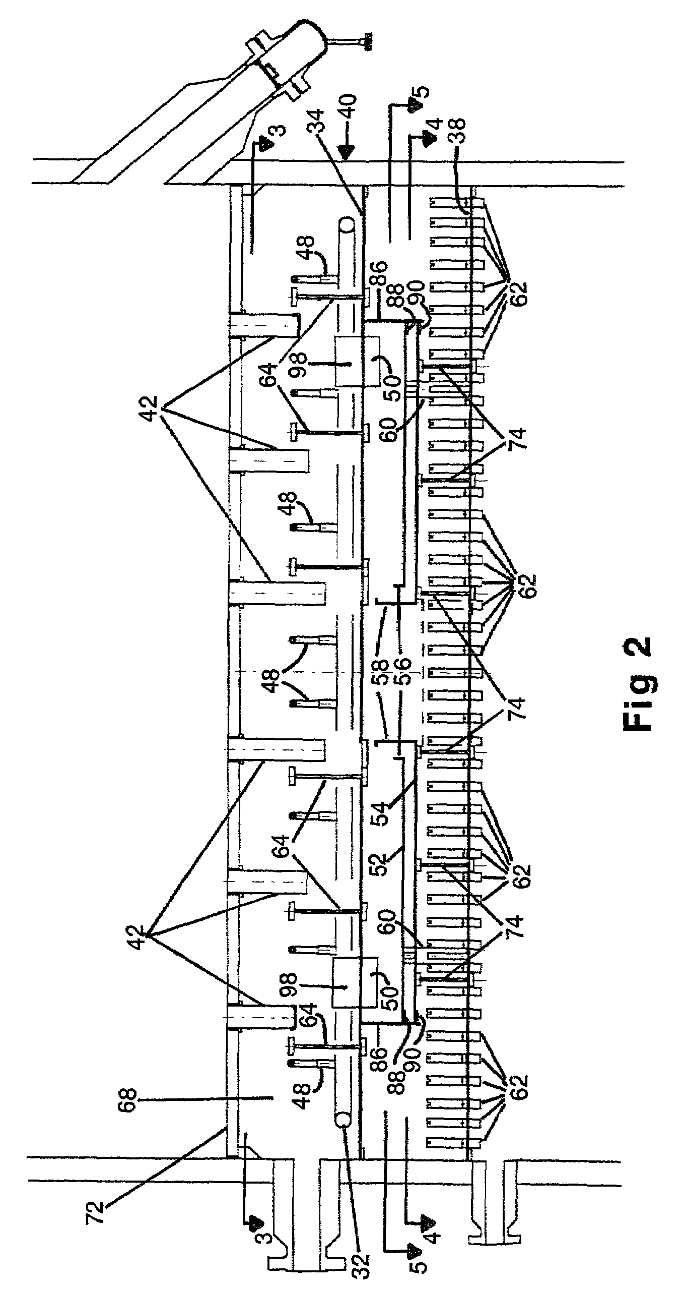
Quench box for a multi-bed, mixed-phase cocurrent downflow fixed-bed reactor
a fixed-bed reactor and quench box technology, which is applied in the direction of transportation and packaging, chemical/physical/physicochemical processes, and excess reactor height, can solve the problems of ineffective means for achieving thermal equilibrium, ineffective inability to provide effective quench gas sweeping action, etc., to reduce the estimated time required for manway removal and reduce the number of manways
- Summary
- Abstract
- Description
- Claims
- Application Information
AI Technical Summary
Benefits of technology
Problems solved by technology
Method used
Image

Examples
case 1
[0068]Example for Calculating the Liquid Residence Time (LRT) in Mixing Chamber[0069] 18 feet inside diameter reactor, low pressure drop revamp[0070]Case 2: 9 feet inside diameter reactor; grassroots installation with liquid flux at 1.5 times that of case 1[0071]Case 3: 6 feet inside diameter reactor, grassroots installation with liquid flux at 1.5 times that of case 1[0072]Case 4: Case with LRT of less than 1 second, 6 feet diameter reactor
[0073]
ParametersCase 1Case 2Case 3Case 4Reactor inside diameter, feet18.009.006.006.00Liquid flow rate, ft3 / s3.081.150.510.51Mixing chamber dimensionDiameter of outer cylinder, inches155.5077.7551.8336.00Diameter of partition pan weir,38.5038.5038.5032.00inchesWeir height of partition pan,2.001.000.750.75inchesDiameter of vapor outlet weir,30.0030.0030.0026.00inchesNumber of drip tubes82.0042.0028.0028.00Number of top slots per drip tube4.004.004.004.00Slot width for the top slots on drip1.251.251.251.25tube, inchesHeight of the top slot base abo...
PUM
| Property | Measurement | Unit |
|---|---|---|
| exit velocity | aaaaa | aaaaa |
| diameter | aaaaa | aaaaa |
| diameter | aaaaa | aaaaa |
Abstract
Description
Claims
Application Information