Protector cover for terminal group

a terminal group and protection cover technology, applied in the direction of insulated conductors, cable terminations, cables, etc., can solve the problems of large space requirements and damage to trunk wires, and achieve the effects of less space, greater utility, and more compact wiring harnesses

Inactive Publication Date: 2006-09-26
SUMITOMO WIRING SYST LTD
View PDF20 Cites 16 Cited by
  • Summary
  • Abstract
  • Description
  • Claims
  • Application Information

AI Technical Summary

Benefits of technology

[0007]In consideration of the above noted shortcomings, the present invention provides a protector cover capable of protecting the collected group spliced terminal ends of multiple wires, and of reducing the amount of space required to locate the spliced terminal ends along the trunk wires.
[0009]In this construction of the present invention, the caps, which cover the terminal group splices, are formed as integral parts of the planar support member. Therefore, placing each terminal group splice within a cap allows multiple terminal group splices to be collectively protected by a single protector cover. Also, by wrapping the planar support member (to which multiple caps are attached) around the circumference of the trunk wires, or by attaching the planar support member to one part of the circumference of the trunk wires, the wiring harness takes up less space and thus allows the trunk wires to be more easily routed through smaller spaces.
[0013]As previously noted, because the present invention provides a construction through which the caps, each of which covers and protects one terminal group splice, are formed as integral parts of the planar support member, placing a terminal group splice in each cap, with each cap being attached to the planar support member, allows a single protector cover to provide protection for multiple terminal group splices. Moreover, wrapping the planar support member (to which multiple caps are attached) around the circumference of the trunk wires, or placing the planar support member over one part of the circumference of the trunk wires, results in a more compact wiring harness, and thus allows the trunk wires to be routed through smaller spaces.
[0014]Furthermore, it is possible to initially manufacture the planar support members as part of a single continuous belt-like structure from which each planar support member can be cut to a length having the desired number of caps, thereby providing greater utility by eliminating the need to individually fabricate protector covers having a number of caps corresponding to the number of terminal group splices.
[0015]Moreover, each of the caps may be formed separately, and curved cap support arms may be formed in alignment at intervals on the flexible planar support member to support the caps inserted therein. This construction increases the utility of the protector cover because various size caps can be used to accommodate terminal group splices of various sizes, thus making it easier to place the caps over the terminal group splices.
[0016]Also, the planar support member may be formed to a C-shape in cross section, thus allowing the planar support member to be pressed onto and elastically grip the circumference of the trunk wires. This construction allows easy attachment of the planar support member to the trunk wires without the need for tape wrapping.

Problems solved by technology

Splice case 1, however, is unable to flex due to its construction of hard synthetic resin, thus creating a problem in that a large amount of space is required to accommodate splice case 1, with wire terminals 6 installed therein, in the vicinity of trunk wires 4.
There is also the possibility that splice case 1, which is constructed of a hard synthetic resin, may interfere with and cause damage to trunk wires 4.

Method used


Image

  • Protector cover for terminal group
  • Protector cover for terminal group
  • Protector cover for terminal group

Examples


first embodiment

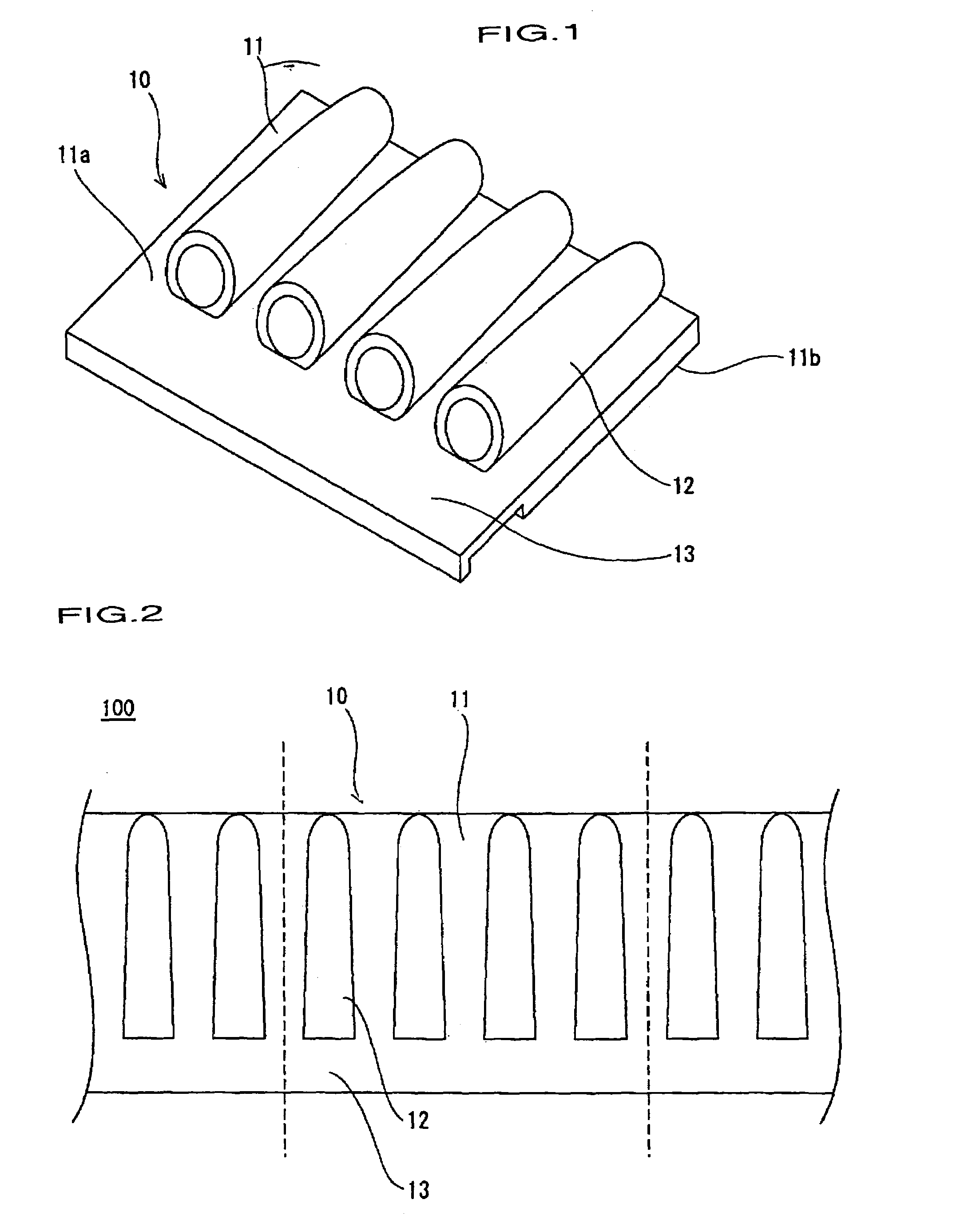
[0031]The following will describe preferred embodiments of the invention with reference to the drawings. FIGS. 1 through 5 illustrate the invention.

[0032]As shown in FIG. 1, terminal group splice protector cover 10 (hereafter referred to as “protector cover 10”) includes four cap tubes 12 provided on surface 11a of flexible planar support member 11, cap tubes 12 utilized as capping members placed over the terminal group splices. Cap tubes 12 are arranged along planar support member 11. One portion of each cap tube 12 may be fixedly joined to the planar support member 11. Lower surface 11b of planar support member 11 is an uninterrupted flat surface to which no cap tubes 12 are attached. One end of each cap tube 12 is open, and taping flange 13 is provided as the portion of planar support member 11 extending beyond the open end of cap tubes 12. Taping flange 13 is a single flange that extends along the entire length of planar support member 11 from one side of cap tubes 12 to the oth...

third embodiment

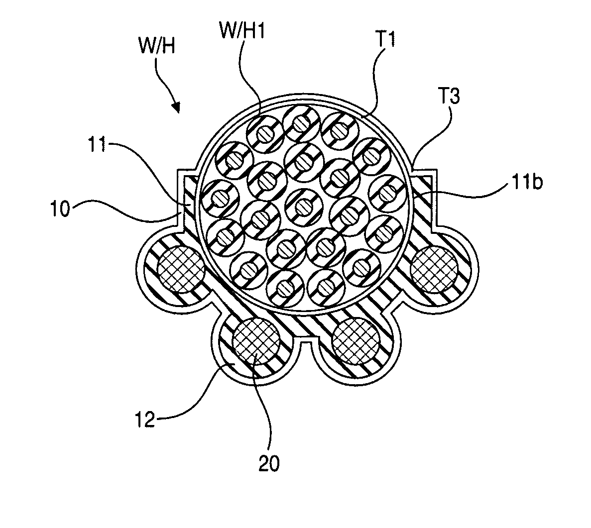
[0044]FIG. 9 describes the invention wherein protector cover 10″ has essentially the same structure as the other embodiments except for being C-shaped in cross section. Planar support member 11″, on which cap tubes 12″ are formed on the external perimeter, has a diameter slightly smaller than the diameter of trunk wires W / H1.

[0045]Protector 10″ is attached to the branch wire terminal ends in the same manner as described in the first embodiment, and as illustrated in FIG. 9B, is able to elastically grip the circumference of trunk wires W / H1 when pressed thereon.

[0046]This third embodiment provides the same functional advantages of the first embodiment but eliminates the need to secure protector cover 10″ with a tape wrapping due to C-shaped planar support member 11″ attaching by gripping the perimeter of trunk wires W / H1. Because the other functions of this third embodiment are essentially similar to those of the first embodiment, descriptions of components and mechanisms of the two ...


PUM

PropertyMeasurementUnit
perimeteraaaaaaaaaa
flexibleaaaaaaaaaa
lengthaaaaaaaaaa

Abstract

A protector cover that protects multiple collected wire terminal group splices while reducing the space occupied by the wire harness by locating the protector cover on the wire harness. The protector cover encloses solder joined terminal group splices formed at the ends of branch wires that separate from trunk wires of a wire harness. Multiple caps, each into which a terminal group splice is inserted, are formed at intervals on one or both sides of a planar support member, and a taping flange is formed as an extension at the open end of the caps. A terminal group splice is inserted into each cap and secured therein by a tape wrapping that encompasses the taping flange and the branch wires. The planar support member is then attached to the circumference of the trunk wires through a tape wrapping.

Description

RELATED APPLICATIONS[0001]The present disclosure relates to subject matter contained in priority Japanese Application No. 2003-404938, filed on Dec. 3, 2003, which is herein expressly incorporated by reference in its entirety.BACKGROUND OF THE INVENTION[0002]1. Field of the Invention[0003]The present invention relates to a protective cover placed over a wire splice, and more particularly to a protective insulated cover provided over collected solder joined ends of multiple electrical wires.[0004]2. Description of the Background Information[0005]As shown in FIGS. 10A–10D, the prior art includes a splice case 1, which is described by Japanese Kokai (Laid Open) Patent H8-148201. Splice case 1 serves as an insulated protective housing covering the solder joined terminal ends of multiple wires of an automotive wire harness. Splice case 1 includes multiple compartments 2, each housing a terminal splice 6 including the solder joined ends of wires 5 which separate from trunk wires 4. After ...

Claims


Application Information

Patent Timeline
Patent Type & Authority Patents(United States)
IPC IPC(8): H02G15/02B60R16/02H01B7/00H01R4/22H01R4/70H02G1/14
CPCH01R4/22
Inventor HATORI, SHOUJI
Owner SUMITOMO WIRING SYST LTD
Why Eureka
Try Eureka