Sensor mounting apparatus for minimizing parasitic stress

a sensor and apparatus technology, applied in the direction of pedestrian/occupant safety arrangement, instruments, tractors, etc., can solve the problems of parasitic stress affecting the sensor output, airbag deployment can be a problem for small children or children, etc., to achieve sufficient robustness, maintain crash worthiness, and minimize parasitic stress

Active Publication Date: 2006-09-26
SENSATA TECHNOLOGIES INC
View PDF16 Cites 68 Cited by
  • Summary
  • Abstract
  • Description
  • Claims
  • Application Information

AI Technical Summary

Benefits of technology

[0007]It is an object of the invention to provide mounting apparatus for a force responsive sensor that will minimize parasitic stress that affects sensor output. It is another object of the invention to provide a stress reducing sensor mounting apparatus that is sufficiently robust to maintain crash worthiness as well as meeting noise / vibration requirements of the seat structure, limited movement criteria and other performance characteristics of the vehicle seat.

Problems solved by technology

For example, airbag deployment can be a problem for small children or children in car seats occupying a front passenger seat.
By way of example, the tracks on opposite sides of the seat may be somewhat out of parallel with each other even when they are within specified tolerances and this can place a moment on the sensors creating a parasitic stress that affects the sensor output.

Method used


Image

  • Sensor mounting apparatus for minimizing parasitic stress
  • Sensor mounting apparatus for minimizing parasitic stress
  • Sensor mounting apparatus for minimizing parasitic stress

Examples


Embodiment Construction

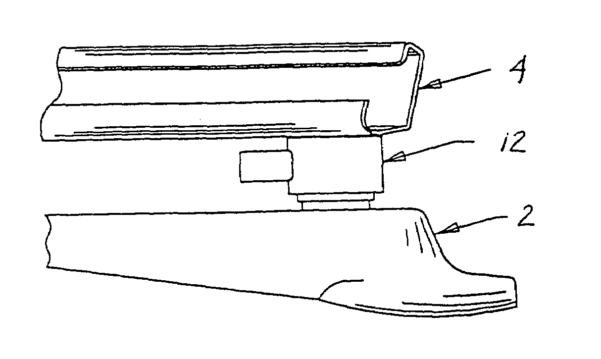
[0016]FIG. 1 shows one possible placement of an occupant weight sensor for use in a vehicle. Occupant weight sensor 12 is shown mounted between a first, broken away frame 2 for fixed attachment to the chassis of a vehicle and a second, seat support frame 4. It will be understood that the sensor could also be mounted at other locations, such as above seat track frames, i.e., between an upper track and a pan frame.

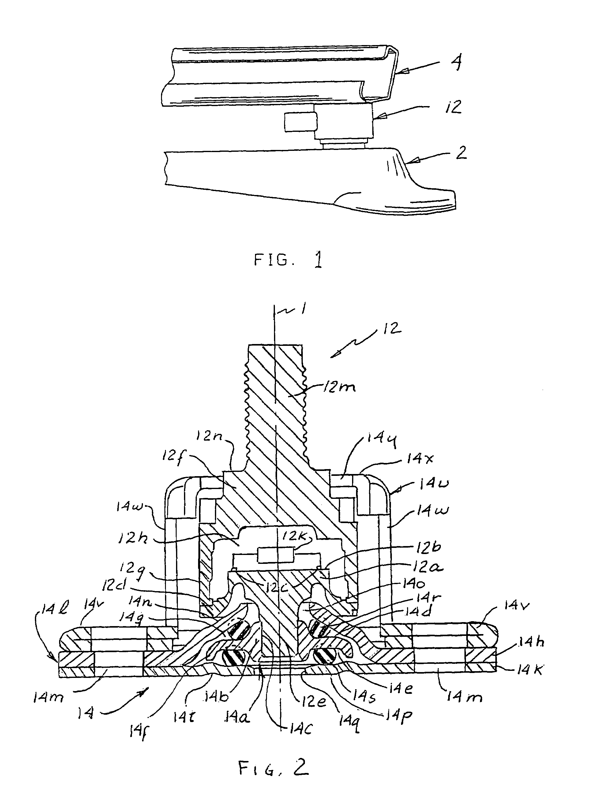
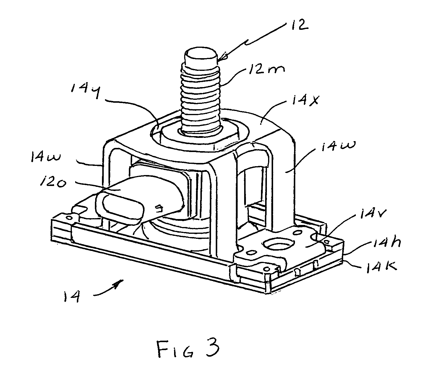
[0017]Sensor 12, shown in FIG. 1, is of the type shown in FIG. 1a of copending, coassigned application Ser. No. 10 / 874,963 referenced above. With reference to FIGS. 2 and 3, sensor 12 comprises a first body 12a of suitable material such as stainless steel having a sense surface 12b on which suitable sensors 12c are disposed. First body 12a is formed with an annular, radially extending flange surface 12d around the periphery of the sense surface and a post 12e extending away from body 12a along a longitudinal axis 1.

[0018]A second body 12f of suitable material such as stainle...


PUM


Abstract

A compliant interface (14,16) for vehicular seat weight sensors minimizes parasitic stresses affecting sensor output. In one embodiment, an integral compliant interface (14) has an annular flange (14a) attached to a post extending from the sensor body with a first compliant member (14r) disposed between the annular flange and an upper elongated flange (14h) of a mounting bracket (14l) and a second compliant member (14s) disposed between the annular plate and a lower elongated flange (14k) to allow pivotal movement of the sensor limited by a motion stop member (14f) of annular flange (14b) engaging the lower flange. An overload cage (14u) may be placed over the sensor and attached to an additional flange (14l) to contain the sensor in the event of a failure of the mount in a catastrophic high speed crash. According to another preferred embodiment, an interface having upper and lower body members are formed with a sensor post receiving bore (16c) for attachment to the post. The body members are formed with spaced apart, radially extending face surfaces, each formed with an annular recess aligned with each other and with a compliant member received therein and fixed to the respective body members and extending beyond the face surfaces. The interface is received through a bore of a support plate to which the sensor is mounted with the compliant members engaging opposite face surfaces of the support plate allowing limited pivotal motion and with a compliant member limiting lateral movement of the interface relative to the support plate.

Description

CROSS REFERENCE TO RELATED APPLICATIONS[0001]U.S. application Ser. Nos. 10 / 874,963 and 10 / 875,018 bothfiled Jun. 23, 2004 and both assigned to the assignee of the present invention contain subject matter related to the subject matter of this application.FIELD OF THE INVENTION[0002]This invention relates generally to apparatus for mounting condition responsive sensors such as force sensors and more particularly to such apparatus for minimizing parasitic stress applied to a sensor used for weighing the occupant of a vehicular seat as an input to a system used to prevent or modify airbag deployment for improved safety of the seat occupant.BACKGROUND OF THE INVENTION[0003]Governmental legislation requires the development of a system capable of sensing information related to front passenger seat occupants and classifying such occupants to the extent necessary to adapt airbag deployment to improve passenger safety. For example, airbag deployment can be a problem for small children or chil...

Claims


Application Information

Patent Timeline
Patent Type & Authority Patents(United States)
IPC IPC(8): G01G21/10B60R21/015B60N2/90G01G19/08G01G19/414
CPCG01G19/4142B60R21/01516Y10S177/09
Inventor DIPAOLA, DAVID J.FRACKELTON, PETER H.HYLAND, DAVID E.MCBRIDE, TIMOTHY M.SMITH, NATHANRESHAMWALA, CHETAKBOYCE, WILLIAM S.BAUTISTA, JONAS M.
Owner SENSATA TECHNOLOGIES INC
Why Eureka
Try Eureka