Electrical interconnect interface and wire harness test and test development system and method

a technology of electrical interconnection and test system, applied in the direction of instrumentation, line-transmission details, line-transmission monitoring/testing, etc., can solve the problems of large and complex wire harnesses, and the connectors themselves can be quite complex, so as to improve the flexibility of test configuration and facilitate rapid and easy construction

Inactive Publication Date: 2006-09-26
THOMAS GEOFFREY L
View PDF2 Cites 41 Cited by
  • Summary
  • Abstract
  • Description
  • Claims
  • Application Information

AI Technical Summary

Benefits of technology

[0010]The ITA has a panel and a second group of connectors, each of which is mounted on the panel. Each contact of each connector of the first group (i.e., the group to which the wire testing machine is connected) is electrically coupled with a contact of a connector of this second group, and at least some of the contacts of the connectors of the first group are coupled to more than one contact of the connectors of the second group (mounted in the ITA panel). Thus, in operation, the test points of the wire testing machine can be electrically coupled to more than one contact of the ITA panel connectors, thereby distributing stimulus signals generated by the wire testing machine and response signals to be received by the wire testing machine over a greater number of ITA panel contacts. This distribution of signals or signal pathways from a smaller number of test points or contacts at the wire testing machine to a larger number of contacts at the ITA panel enhances test configuration flexibility, as will become apparent from the detailed description below.
[0012]Each adapter module also has a second connector that is mateable with a connector of the wire harness or UUT. A cable or other suitable electrical pathway couples this second connector with the first connector that plugs into one or more of the ITA panel connectors as described above. In some embodiments of the invention, the signal pathways represented by the wire testing machine Tester interface connectors can be uniformly distributed or distributed in a suitable pattern over some or all of the area of the ITA panel so as to enhance test configuration flexibility. For example, a test point on the wire testing machine can be coupled to every third contact in a rectangular array of ITA panel connectors or to one contact of each connector, thereby making the pathway available to an adapter module regardless of where on the panel it is plugged into. For convenience, each location on the panel into which an adapter module can be plugged may be referred to as a “zone,” and the zones numbered or otherwise labeled with suitable indicia on the panel.
[0013]A manufacturer of ITAs in accordance with the present invention can provide its customers with kits that comprise connectors conforming to the selected standard so that the customer can quickly and easily build adapter modules to test any desired wire harness. To build an adapter cable, a user need only obtain a connector of a type present in the UUT and couple it with a cable or other suitable electrical pathway to one of the standard connectors provided in the kit. Unlike a conventional adapter cable, which may comprise a complex network of interconnected connectors of different types, an adapter module of the present invention comprises one standard connector coupled with one connector mateable with a connector of the UUT. This arrangement and standardization enables re-use of the adapter cable when the user needs to test a different wire harness that has the same type of connector as previously tested wire harness.

Problems solved by technology

Some wire harnesses, such as those used in aircraft, ships, mass transit vehicles and other large vehicles, can be quite large and complex, comprising many individual cables of various lengths, with various types of connectors.
The connectors themselves can be quite complex, such as the cylindrical connectors commonly used in military and aerospace vehicles, which typically have from a dozen to well over 100 contacts housed in cylindrical shell with a male or female bayonet or threaded coupling mechanism.

Method used


Image

  • Electrical interconnect interface and wire harness test and test development system and method
  • Electrical interconnect interface and wire harness test and test development system and method
  • Electrical interconnect interface and wire harness test and test development system and method

Examples


Embodiment Construction

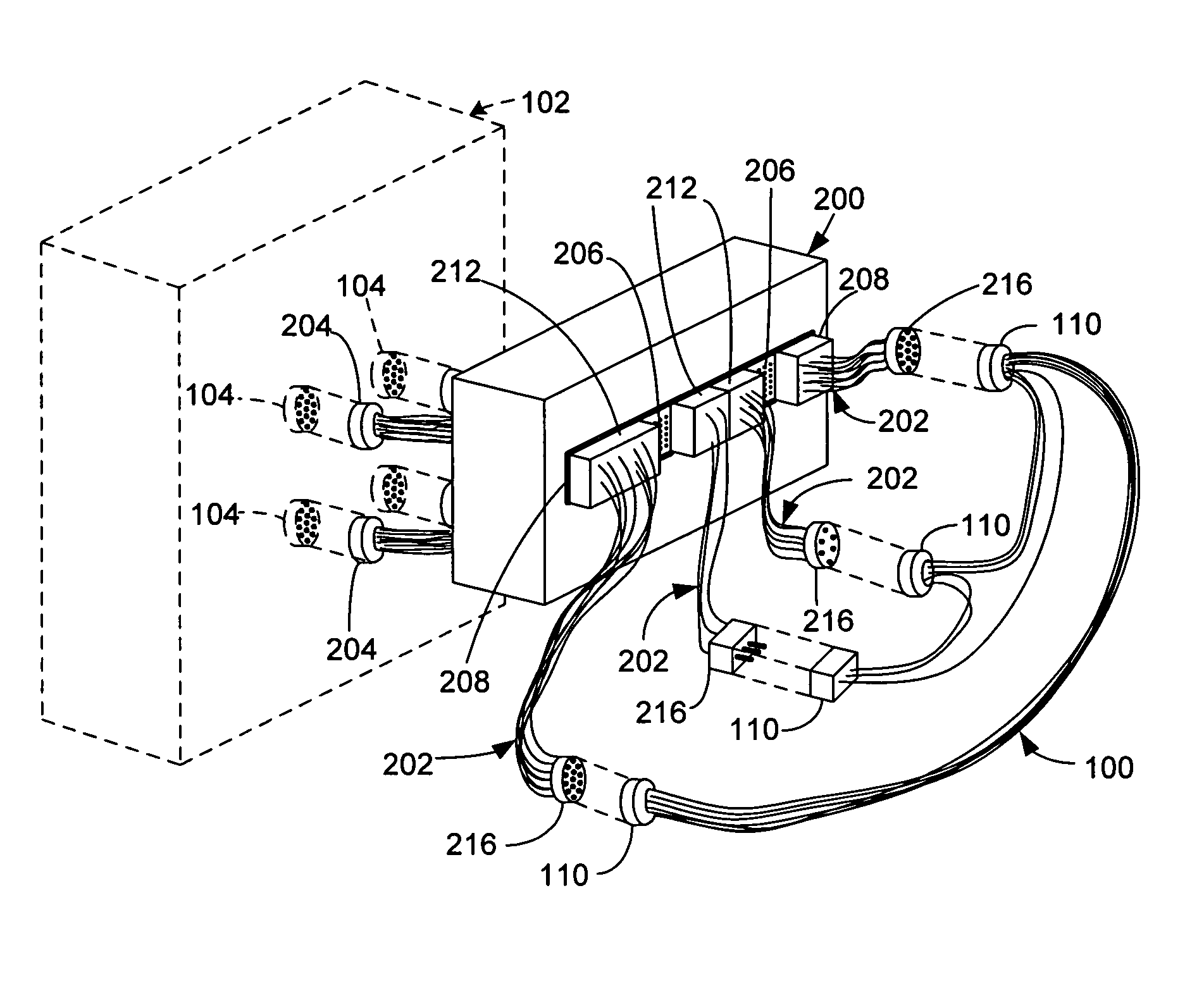
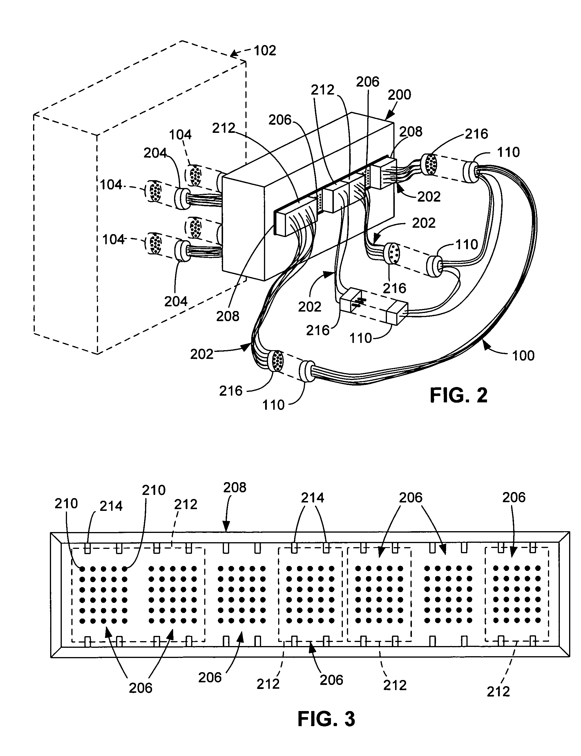
[0024]As illustrated in FIG. 2, a testing apparatus comprises an interface test adapter (ITA) 200 and a plurality of adapter modules 202. In the illustrated embodiment of the invention, this testing apparatus couples or interfaces the wire harness unit-under-test (U UT) 100 with a conventional wire testing machine 102. Such automated wire testing machines 102, which include all of the switching and control electronics (not shown for purposes of clarity) needed to perform automated tests upon wire harnesses, are well-known in the art, commercially available from a number of sources, and therefore not described in further detail herein (in this patent specification).

[0025]ITA 200 includes a first group of connectors 204 that can be plugged into or otherwise mated or connected to (as indicated by dashed line) connectors 104 of the same type on the front panel of wire testing machine 102. As used herein, the term “type” with reference to a connector refers to the electrical and mechanic...


PUM


Abstract

An automated wire testing system includes adapter modules that couple a wire harness under test with an interface test adapter. The interface test adapter (ITA) is coupled to or integrated with an automated wire testing machine. The ITA has a panel into which a standardized connector can be plugged in any of a number of positions. Stimulus / response paths originating at test points on the wire testing machine are distributed over a larger number of contacts on the panel connectors to provide flexibility. Adapter modules for any wire harness can readily be built using the standardized connector.

Description

BACKGROUND OF THE INVENTION[0001]1. Field of the Invention[0002]The present invention relates generally to automated test equipment and, more specifically, to wire testing systems and methods.[0003]2. Description of the Related Art[0004]Automated test equipment (ATE) is computer-controlled equipment that tests electronic devices for functionality or performance. One category of ATE includes automated wire testing machines for testing cables, wire harnesses and other complex wired assemblies. Wire testing machines are also variously referred to in the art to which the invention relates as wire testers and wire analyzers.[0005]The term “wire harness” or “wiring harness” is commonly used to refer to an assembly comprising a bundle of electrical cables with electrical connectors at their ends. Some wire harnesses, such as those used in aircraft, ships, mass transit vehicles and other large vehicles, can be quite large and complex, comprising many individual cables of various lengths, wi...

Claims


Application Information

Patent Timeline
Patent Type & Authority Patents(United States)
IPC IPC(8): G01R31/02G01R31/58
CPCG01R31/041G01R31/024G01R31/045G01R31/69G01R31/67G01R31/58
Inventor THOMAS, GEOFFREY L.
Owner THOMAS GEOFFREY L
Why Eureka
Try Eureka