Work machine display system

a display system and work machine technology, applied in mechanical machines/dredgers, analogue processes for specific applications, instruments, etc., can solve the problem that the position information provided by this type of display system may not be sufficient to allow the operator to efficiently opera

Active Publication Date: 2006-09-26
CATERPILLAR INC
View PDF8 Cites 26 Cited by
  • Summary
  • Abstract
  • Description
  • Claims
  • Application Information

AI Technical Summary

Problems solved by technology

However, the positional information provided by this type of display system may be insufficient to allow the operator to efficiently excavate a geographic location.
In addition, this type of display system does not indicate the current surface level of the current geographic location relative to the desired surface configuration.

Method used


Image

  • Work machine display system
  • Work machine display system
  • Work machine display system

Examples


Embodiment Construction

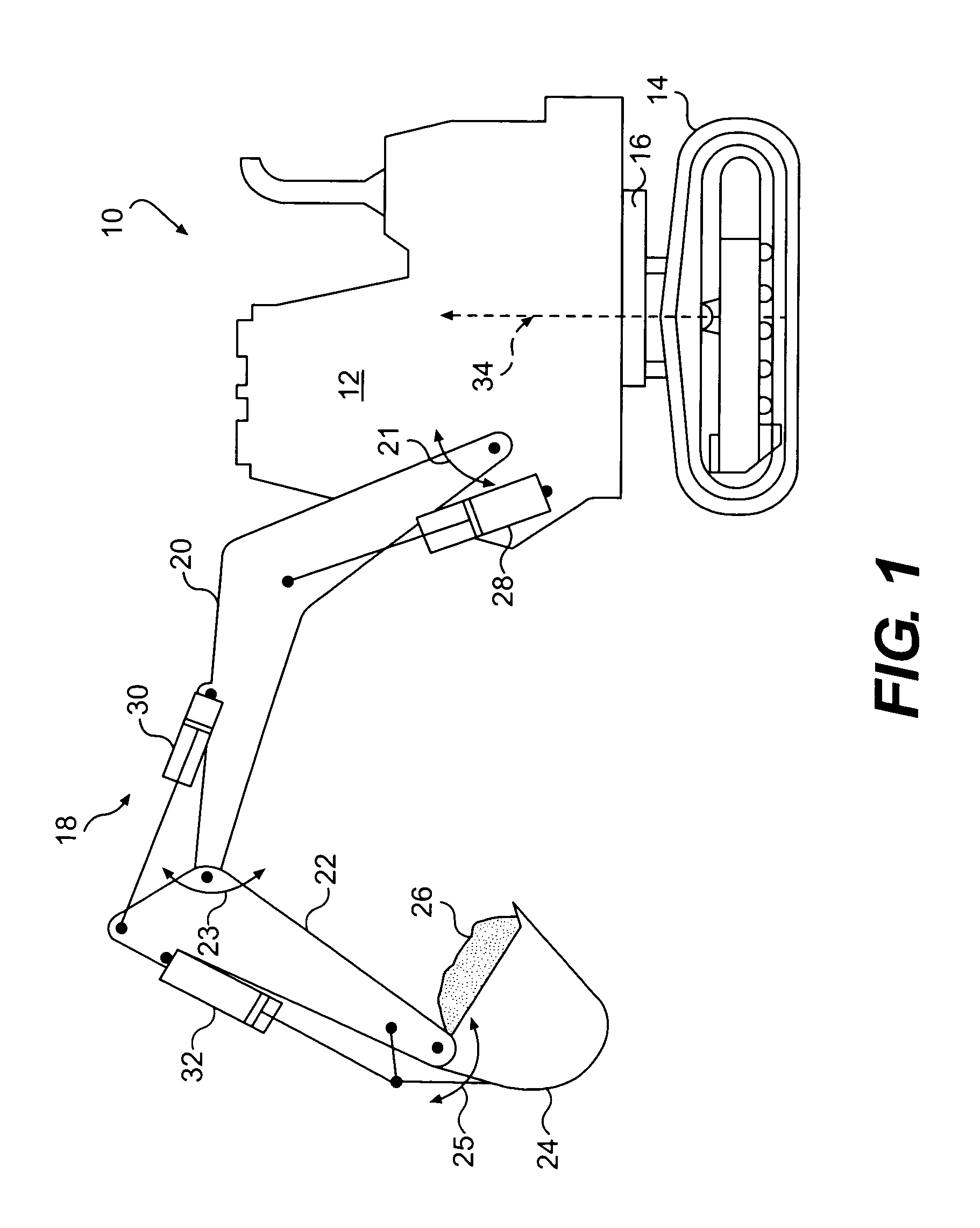
[0015]An exemplary embodiment of a work machine 10 is illustrated in FIG. 1. Work machine 10 may be any type of machine commonly used to excavate earth, or other material, from a geographic location, such as, for example, an excavator or a backhoe. For the purposes of the present disclosure, the term “geographic location” is intended to include any land feature or terrain that may be excavated to shape the surface of the terrain to conform to a desired surface configuration. For example, work machine 10 may be used to excavate material from a construction site or mining site.

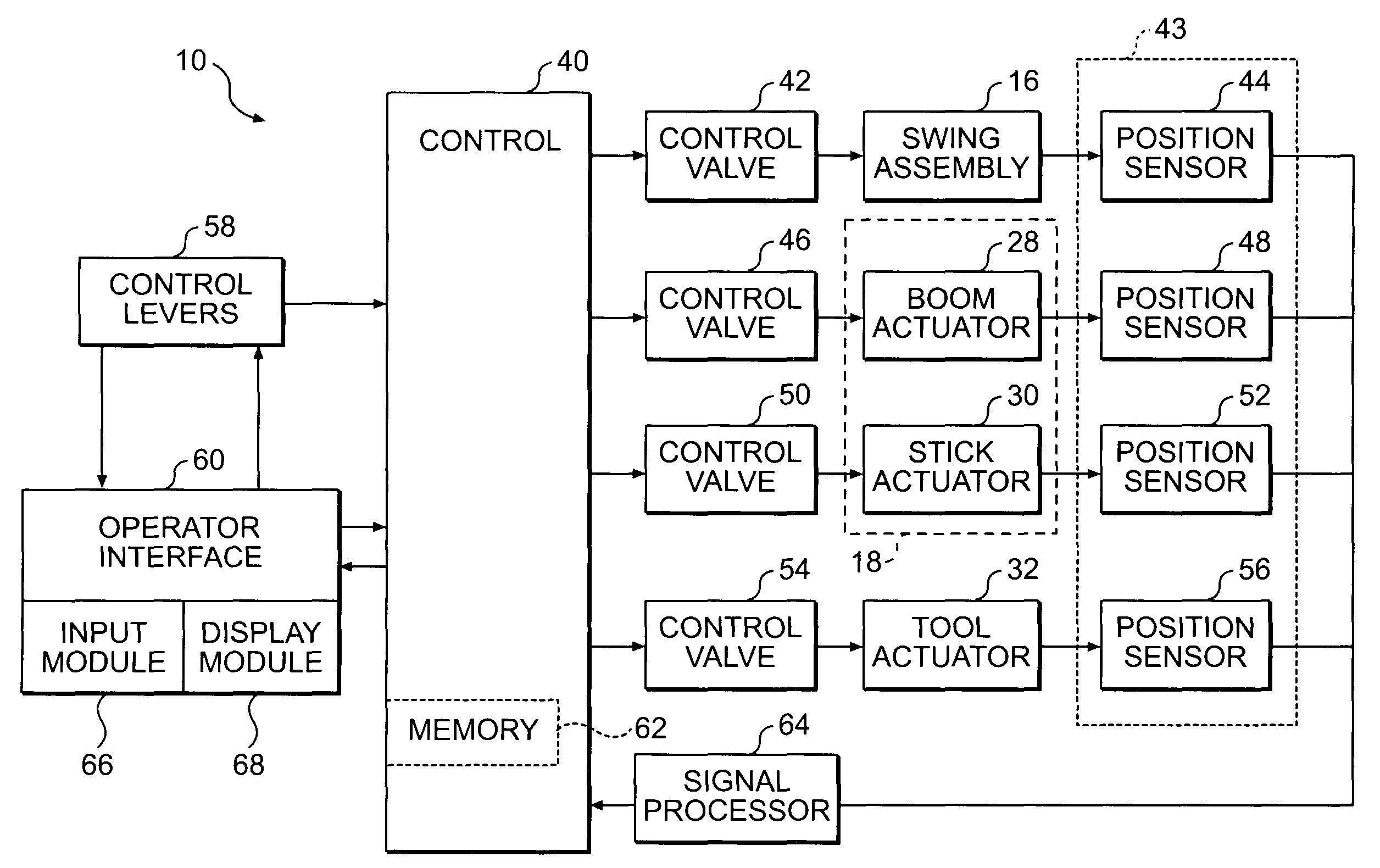
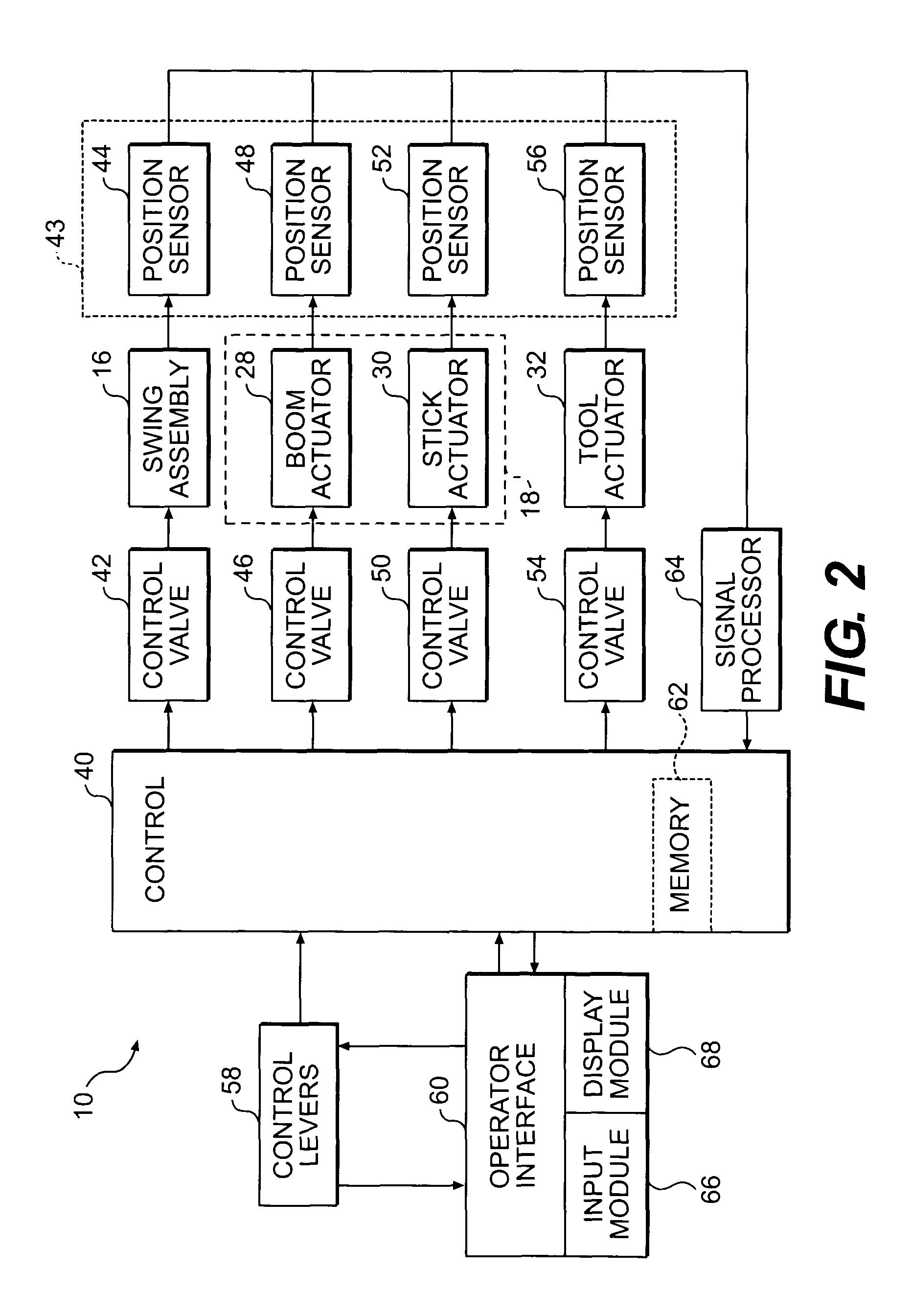
[0016]As illustrated in FIG. 1, work machine 10 includes a housing 12 that may include a seating area for an operator. Housing 12 may be mounted on a swing assembly 16 that is configured to rotate or pivot housing 12 about a vertical axis 34. Swing assembly 16 may include a hydraulic actuator, such as, for example, a fluid motor or a hydraulic cylinder, that pivots housing 12 about vertical axis 34. Pressurized ...


PUM


Abstract

A display system and method for a work machine is provided. A terrain map indicative of a current surface configuration for a geographic location is displayed. The display of the terrain map includes a plurality of elevation segments. Each of the plurality of elevation segments has an actual surface elevation value for a discrete area of the geographic location. A position of a ground engaging tool operatively connected to the work machine is monitored. A current elevation of the ground engaging tool is identified. The display of the elevation segment corresponding to the location of the ground engaging tool is updated when the current elevation of the ground engaging tool indicates a change in the actual surface elevation value for the elevation segment corresponding to the location of the ground engaging tool.

Description

TECHNICAL FIELD[0001]The present invention is directed to a display system and, more particularly, to a display system for a work machine.BACKGROUND[0002]Work machines are commonly used to excavate earth or other material from a geographic location such as, for example, a construction site. A work machine typically includes a ground engaging tool, such as, for example, a bucket or shovel to remove earth or material from the surface of the geographic location. A work machine operator may control the movement of the ground engaging tool to excavate earth or other material from the geographic location to shape the surface to conform to a desired surface configuration.[0003]The ground engaging tool of a work machine may be powered by a hydraulic system. A typical hydraulic system includes a series of hydraulic actuators, which may be, for example, hydraulic cylinders, that are interconnected with a work implement linkage that mounts the ground engaging tool. The hydraulic system may als...

Claims


Application Information

Patent Timeline
Patent Type & Authority Patents(United States)
IPC IPC(8): G08B21/00E02F9/26G08G1/0962
CPCE02F9/26
Inventor SAHM, WILLIAM CHARLESKOEHRSEN, CRAIG LAWRENCE
Owner CATERPILLAR INC
Why Eureka
Try Eureka