Light amount control apparatus, photographing apparatus, and filter

a technology of light amount control and photographing equipment, applied in the field of light amount control equipment, can solve the problems of deteriorating continuity of exposure control, no high-resolution images can be obtained, and inability to achieve well the original image forming performance, etc., and achieve the effect of large degree of freedom of light amount control

Inactive Publication Date: 2006-09-26
CANON KK
View PDF11 Cites 23 Cited by
  • Summary
  • Abstract
  • Description
  • Claims
  • Application Information

AI Technical Summary

Benefits of technology

[0023]The present invention has been made in consideration of the above situation, and has as its object to provide a small-sized, inexpensive light amount control apparatus, photographing apparatus, and filter having a large degree of freedom of light amount control, and capable of holding a predetermined shape of an aperture during stopping down.

Problems solved by technology

This makes it impossible to well achieve the original image forming performance of the photographing optical system or the high pixel capability of the image sensing means, so no high-resolution images can be obtained.
Unfortunately, the above conventional techniques have the following drawbacks.
In particular, if the ND filters suddenly enter when a dark scene changes to a bright scene during motion image photographing, the continuity of exposure control deteriorates.
This significantly degrades the naturalness of the reproduced motion image.
However, a circular stop aperture can not be obtained by this mechanism, so blurred images have unnatural shapes.
This produces a light amount loss at open aperture.
Also, since the aperture blades and ND filter are driven together, the degree of freedom of control of the ND filter is lost.
Therefore, no multi-step light amount control by the ND filter can be performed.
In the conventional technique disclosed in Japanese Patent Laid-Open No. 2000-106649, the rhombic shape of the stop aperture makes the shapes of blurred images unnatural.
Also, since the strip-like ND filter requires a large accommodating space, the size of the whole apparatus increases.
That is, the use of an open aperture having a large aberration is limited, or the use of a small aperture which increases the influence of diffraction is limited, thereby preventing deterioration of the image quality and obtaining high-resolution images.
Unfortunately, the above conventional techniques still have the following drawbacks.
This produces a light amount loss at open aperture.
This makes a blurred image unnatural when an object having a large distance difference is photographed.
Accordingly, this structure is particularly unsuited to still image photographing requiring high-quality images.
However, no light amount control using an ND filter is disclosed, and the prevention of small-aperture diffraction is unsatisfactory.

Method used


Image

  • Light amount control apparatus, photographing apparatus, and filter
  • Light amount control apparatus, photographing apparatus, and filter
  • Light amount control apparatus, photographing apparatus, and filter

Examples


first embodiment

(First Embodiment)

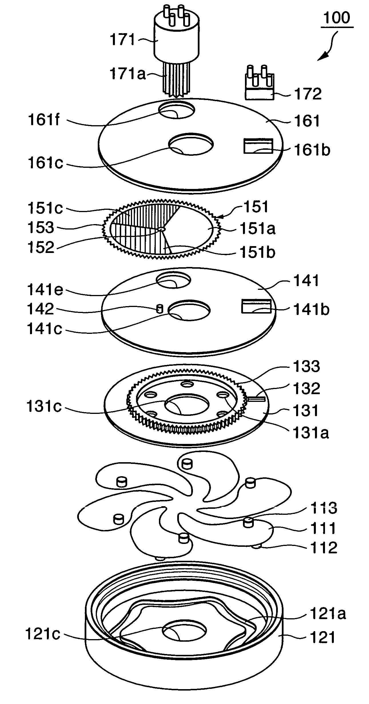
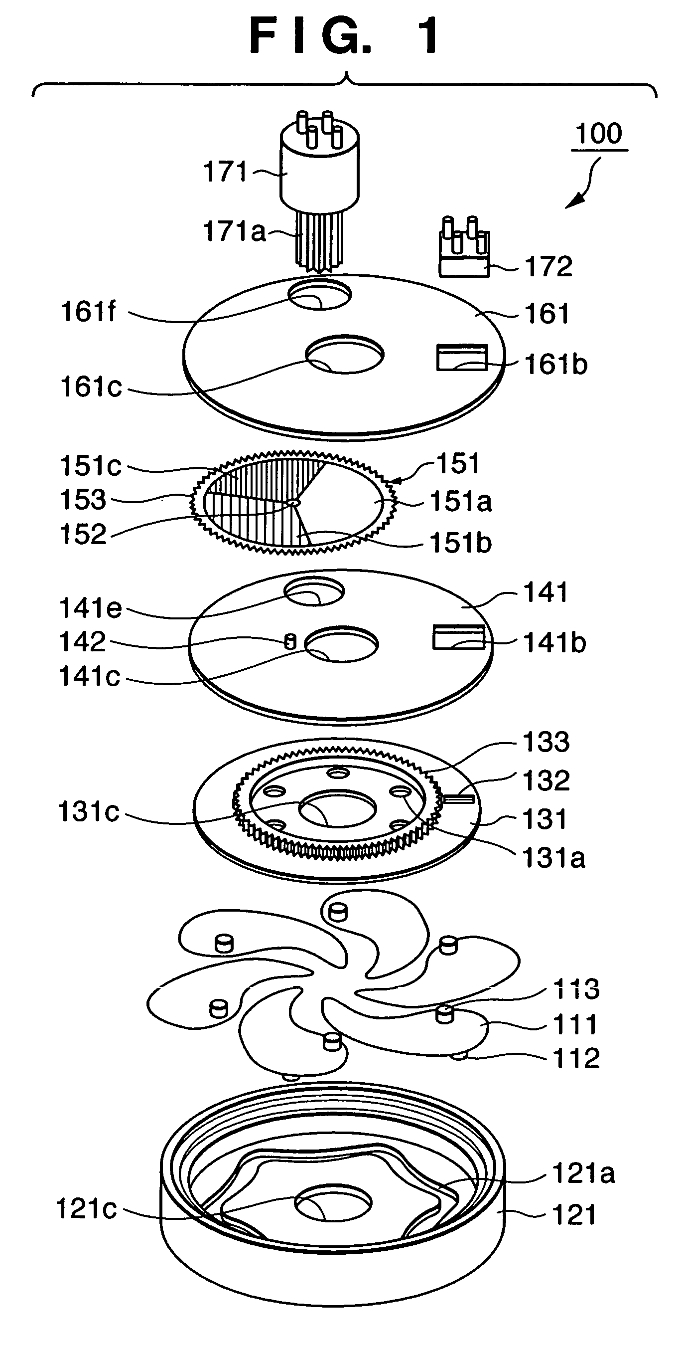
[0064]FIGS. 1 to 11C are views related to the first embodiment.

[0065]FIG. 1 is an exploded perspective view of the main parts of a light amount control apparatus 100 according to this embodiment. In FIG. 1, reference numeral 111 denotes an aperture blade having light-shielding properties over the entire region. Pins 112 and 113 to be driven stand upward from the lower and upper surfaces, respectively, of the aperture blade 111. A stop aperture is formed by using six aperture blades 111 having the same shape. As the number of the aperture blades 111 increases, the aperture shape becomes close to a circle during stopping down, and this improves the naturalness of blurred images and reduces diffraction at the apexes of the polygonal aperture. However, the manufacturing cost also increases. In the stop mechanism of this type, therefore, the number of aperture blades is preferably 5 to 9. As shown in FIG. 1, this embodiment uses the six aperture blades to optimize the s...

second embodiment

(Second Embodiment)

[0162]In the light amount control apparatus used in the first embodiment, the aperture blades and ND filter are driven by one actuator. In the second embodiment described below, aperture blades and ND filter are driven by independent actuators.

[0163]FIG. 12 is an exploded perspective view for explaining the structure of a light amount control apparatus 200 of the second embodiment. FIG. 12 corresponds to FIG. 1 of the first embodiment.

[0164]In FIG. 12, reference numeral 211 denotes an aperture blade having light-shielding properties over the entire region. Pins 212 and 213 to be driven stand upward from the lower and upper surfaces, respectively, of the aperture blade 211. A stop aperture is formed by using six aperture blades 211 having the same shape.

[0165]Reference numeral 221 denotes a base plate for holding the aperture blades 211. In the center of the planar bottom surface, an opening 221c which defines the maximum diameter of a light beam at open aperture i...

third embodiment

(Third Embodiment)

[0190]In the ND filter used in the second embodiment described above, a disk-like filter is divided into a plurality of regions to give different optical densities to these regions, and the optical density distribution of each divided region is uniform. In an ND filter of the third embodiment described below, however, the optical density changes step by step or continuously along the circumference of a disk-like filter.

[0191]FIG. 17A is a plan view for explaining details of the optical density distribution of an ND filter 351 of the third embodiment. FIG. 17A corresponds to FIG. 13 of the second embodiment. A disk-like ND filter 351 has the same mechanical arrangement as that of the ND filter 151 of the first embodiment and the ND filter 251 of the second embodiment. That is, the ND filter 351 is obtained by forming an ND pattern (to be described later) on a transparent resin film, for example, a PET (PolyEthylene Terephthalate) film about 0.1 mm thick by inkjet pr...


PUM


Abstract

It is an object of this invention to independently control the F-number and the number of light attenuation steps of a multi-density ND filter by using a light amount control apparatus using an iris stop and the ND filter. The iris stop mechanism made up of a plurality of aperture blades and the ND filter having a multi-density pattern are stacked in a single unit. This simultaneously realizes continuous control of the F-number, multi-step control of the light attenuation ratio of the ND filter, a substantially circular stop aperture, and a uniform transmittance distribution in the stop aperture. In the first embodiment, the driving region of an actuator is divided into an ND control region and aperture control region. This makes it possible to independently control the F-number and the number of ND steps by the single actuator.

Description

FIELD OF THE INVENTION[0001]The present invention relates to a light amount control apparatus having a light amount attenuating function, a photographing apparatus, and a filter.BACKGROUND OF THE INVENTION[0002]Conventionally, a video camera which records motion images on a magnetic tape medium by using an image sensing means such as a CCD (Charge-Coupled Device) or a CMOS (Complementary Metal-Oxide Semiconductor) and a digital still camera which records still images on a solid memory medium by using a similar image sensing means have been produced. Recently, as the capacity of the solid memory medium is increased and the speed and performance of an image signal processor of a photographing apparatus are improved, photographing apparatuses having functions of both motion image photographing and still image photographing are also beginning to be widely used. On the other hand, as the interval between unit light-receiving portions, that is, a so-called pixel pitch of an image sensing ...

Claims


Application Information

Patent Timeline
Patent Type & Authority Patents(United States)
IPC IPC(8): G02B26/02G03B7/00G02B5/00G02B5/20G03B9/06G03B11/00
CPCG02B5/205G02B5/005
Inventor ONUKI, ICHIROMIYAZAKI, TAKESHIKASHIWAZAKI, AKIONAMAZUE, ERIKO
Owner CANON KK
Why Eureka
Try Eureka