Electrostatic discharge protection device comprising several thyristors

Active Publication Date: 2006-09-26
CENT NAT DE LA RECHERCHE SCI +1
View PDF8 Cites 17 Cited by
  • Summary
  • Abstract
  • Description
  • Claims
  • Application Information

AI Technical Summary

Benefits of technology

[0014]Another advantage of the present invention lies in the possibility of using thyristors which each have a limited conduction capability and which consequently have small dimensions more easily compatible with the processes used for fabricating the devices in which they will be incorporated.
[0015]In one particular embodiment of the invention, the triggering function of the control circuit is implemented with a triggering transistor having a control input connected to an output of the detection function, a first electrode connected to the output of the control circuit, and a second electrode connected to a first of said nodes. With this embodiment, the current for triggering the thyristors is not directly an avalanche current in a junction or a snapback current of a transistor.
[0016]Preferably, said first electrode of the triggering transistor is connected to the output of the control circuit via a resistor. This resistor partially isolates the control circuit from the thyristors, in such a way that the flow of electric charges intended to be drained away is partly limited to the thyristors. Thus, the control circuit itself is protected against possible damage caused by particularly large electrostatic discharge currents.
[0017]Optionally, the triggering function may furthermore include a stabilizing transistor having a control input connected to the output of the detection function, a first electrode connected

Problems solved by technology

A drawback of this type of electrostatic protection based on avalanche or snapback effects is due to the fact that the thresholds at which these effects appear depend on the densities of the electrical dopings produced.
Such protection means become inefficient when these thresholds are too high in relation to certain characteristics of the electrical circuits to be

Method used


Image

  • Electrostatic discharge protection device comprising several thyristors
  • Electrostatic discharge protection device comprising several thyristors
  • Electrostatic discharge protection device comprising several thyristors

Examples


Example

DETAILED DESCRIPTION OF THE DRAWINGS

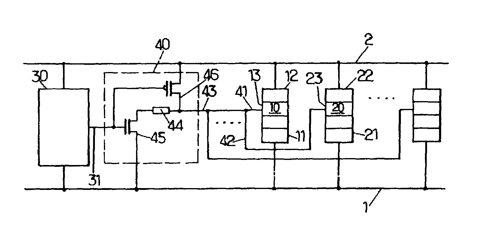
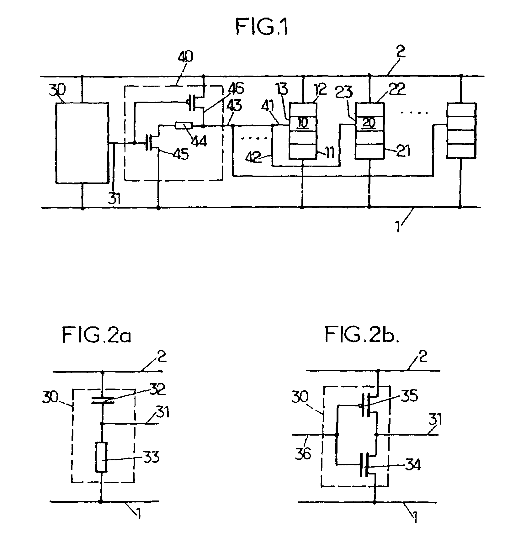
[0028]FIG. 1 shows an electrostatic discharge protection device placed between two nodes 1 and 2 of an electrical circuit (not shown). The nodes 1 and 2 may be the output terminals of an electrical voltage supply, for example a DC supply, the node 1 being the negative terminal and the node 2 being the positive terminal. They may also be two tracks of a binary-signal transport bus, the node 1 being connected to a reference track and the node 2 being connected to a track carrying a signal corresponding to a positive or zero voltage with respect to the reference track. The foregoing present examples only and are not intended to be limiting or restricting of the application of the present invention.

[0029]At least two SCRs (thyristors) 10, 20 are connected by their respective cathodes 11, 21 to the node 1 and by their respective anodes 12, 22 to the node 2.

[0030]The respective control terminal triggers 13, 23 of the SCRs 10, 20 are connected to the out...


PUM


Abstract

An electrostatic discharge protection device comprises several thyristors which are connected in parallel between two nodes of an electrical circuit. It also includes a control circuit having an output connected to the control trigger terminal input of each of the thyristors. In response to an abnormal variation in a voltage between the two nodes being detected, the control circuit initiates a triggering current on the output so as to trigger the thyristors to conduct current between the two nodes. Preferably, the thyristors are arranged in a semiconductor substrate so as to have low hold voltages and small geometrical dimensions.

Description

CROSS-REFERENCE[0001]The present application claims foreign priority from French Patent Application Number 02 05009 filed Apr. 22, 2002, the disclosure of which is hereby incorporated by reference.BACKGROUND OF THE INVENTION[0002]1. Technical Field of the Invention[0003]The present invention relates to devices for protecting integrated electrical circuits against electrostatic discharges. It relates more particularly to such protection devices comprising several thyristors or, equivalently, one thyristor produced in segmented (“multi-finger”) form. For the case in question, that of protecting integrated electrical circuits, the protection device is incorporated into the same substrate as the protected circuit.[0004]2. Description of Related Art[0005]Many electrical circuits, depending on their use, their sensitivity or their installation, need to be protected from being damaged by possible electrostatic discharges. Such discharges are caused, for example, by an operator touching par...

Claims


Application Information

Patent Timeline
IPC IPC(8): H02H9/00H01L27/02
CPCH01L27/0262
Inventor SALOME, PASCALDOURNELLE, STEPHANIEAZAIS, FLORENCECAILLARD, BENJAMINNOUET, PASCAL
Owner CENT NAT DE LA RECHERCHE SCI
Why Eureka
Try Eureka