Lithium microbattery provided with a protective envelope, and method for producing one such microbattery

a technology of lithium anode and lithium compound, which is applied in the direction of non-aqueous electrolyte accumulator electrodes, electrical apparatus, electrochemical generators, etc., can solve the problems of long and fastidious production of lithium anode and lithiated compound-based electrolyte, harmful to battery operation, and cannot be used with lithium anode which could be damaged,

Inactive Publication Date: 2007-03-01
COMMISSARIAT A LENERGIE ATOMIQUE ET AUX ENERGIES ALTERNATIVES
View PDF16 Cites 40 Cited by
  • Summary
  • Abstract
  • Description
  • Claims
  • Application Information

AI Technical Summary

Benefits of technology

[0008] It is an object of the invention to provide a lithium microbattery comprising a protective envelope remedying the shortcomings set out above and in particular enabling the lithium microbattery to be produced on substrates comprising integrated circuits and preferably with a known technological process.

Problems solved by technology

Penetration of oxygen, nitrogen, carbon dioxide and humidity into microbatteries comprising a metallic lithium anode and a lithiated compound-based electrolyte is known to be harmful to operation of the batteries.
Such an envelope protects the battery against heat, gases and liquids, but production thereof is long and fastidious and requires two annealings at temperatures of more than 200° C. Annealings at temperatures of more than 200° C. are however only acceptable for batteries comprising an anode made from lithiated materials.
They can in fact not be used with a lithium anode which could be damaged at temperatures of more than 200° C.
These materials do however have a hardness and a thickness that do not enable the battery to be put under pressure when encapsulation thereof is performed.

Method used


Image

  • Lithium microbattery provided with a protective envelope, and method for producing one such microbattery
  • Lithium microbattery provided with a protective envelope, and method for producing one such microbattery
  • Lithium microbattery provided with a protective envelope, and method for producing one such microbattery

Examples


Embodiment Construction

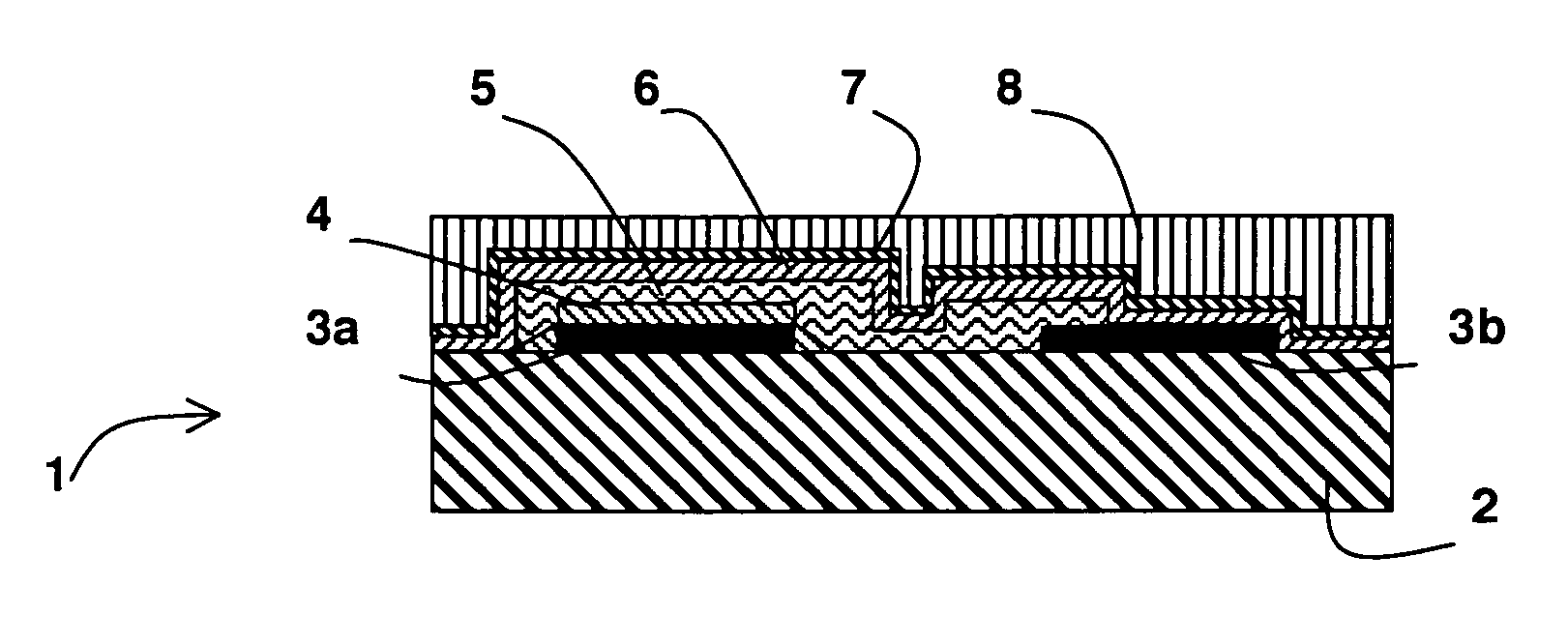
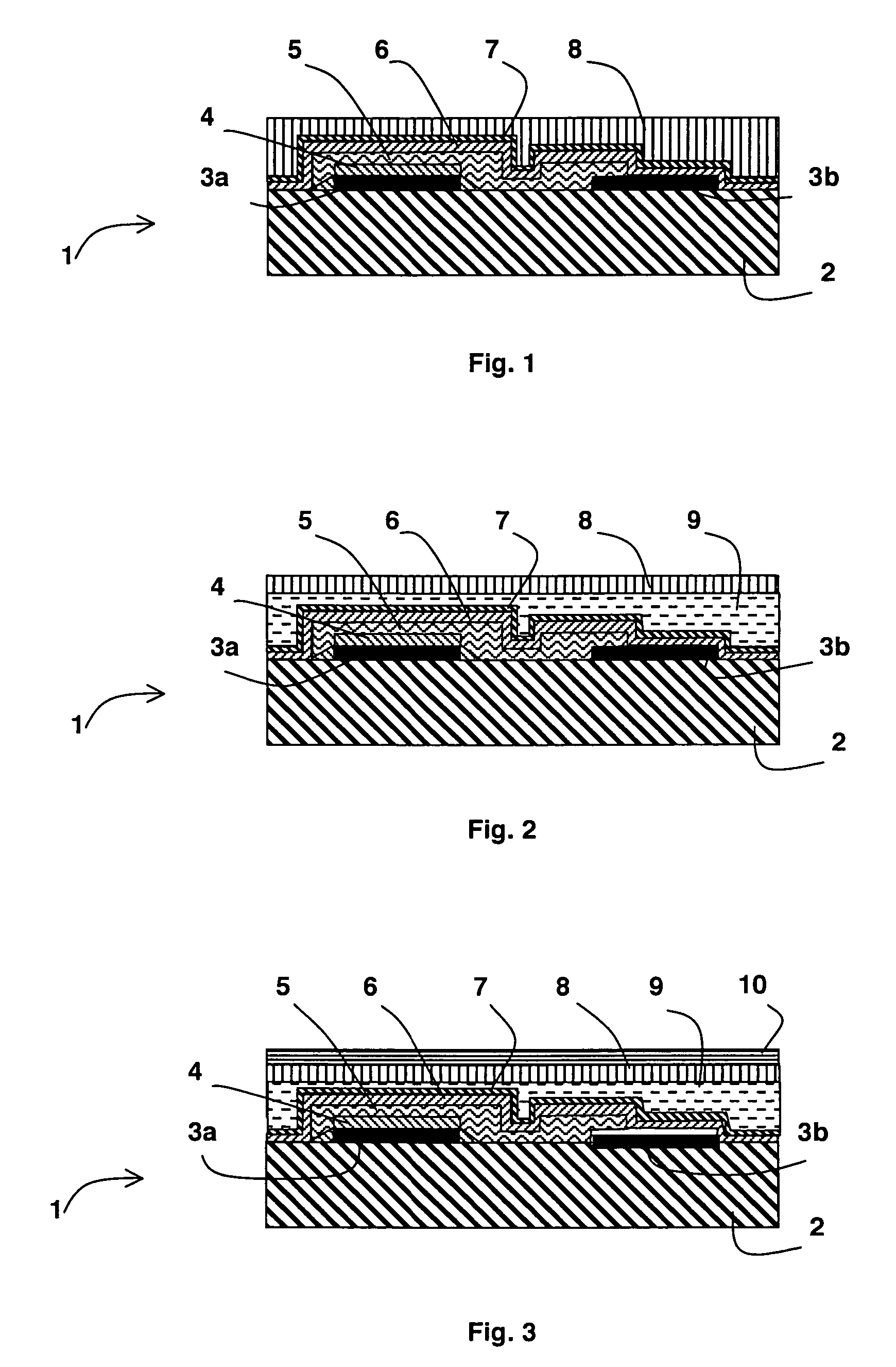
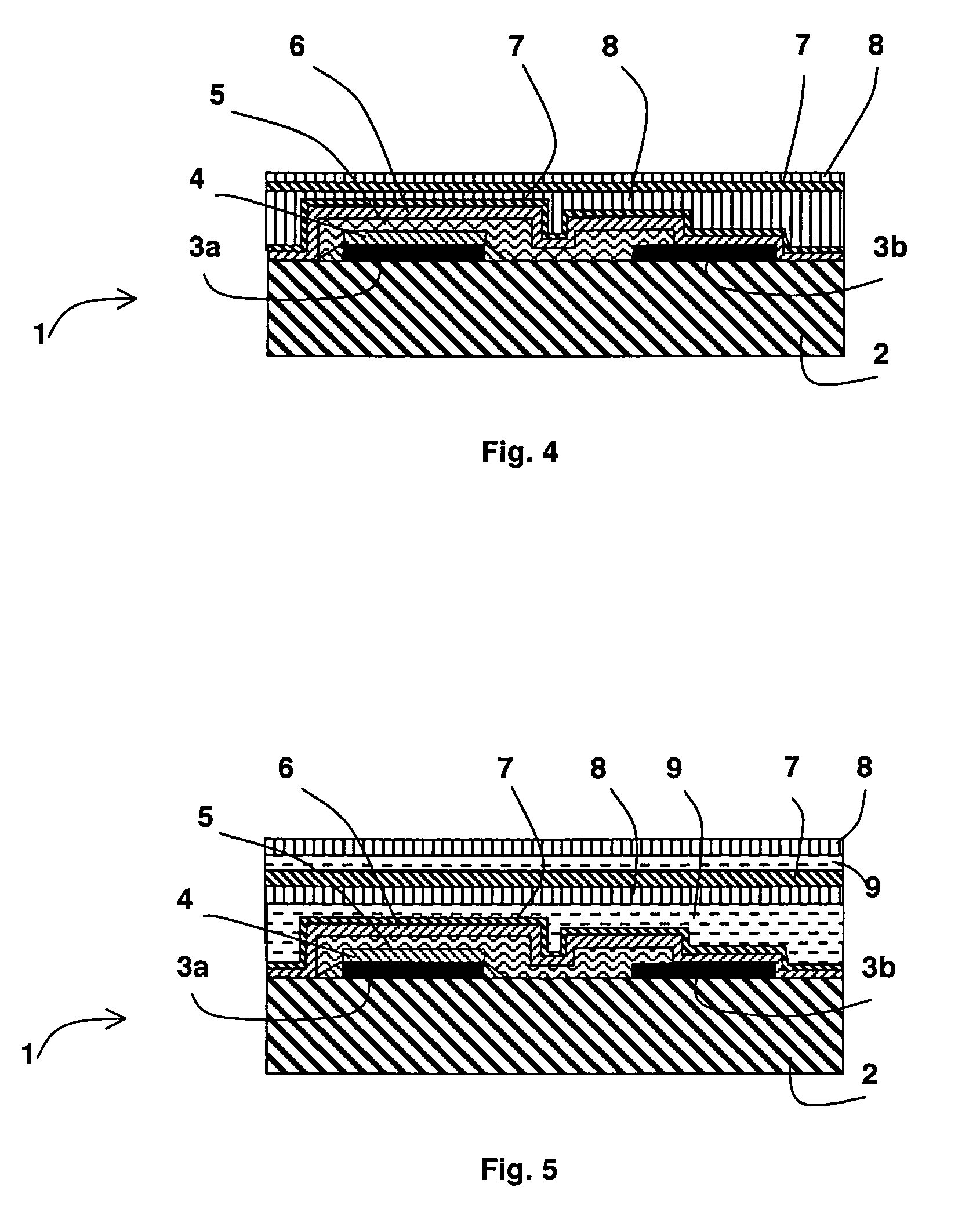
[0018] As represented in FIG. 1, a lithium microbattery 1 comprises a substrate 2 on which there are successively arranged, in the form of thin layers:

[0019] first and second current collectors 3a and 3b, the first current collector 3a being totally covered by a cathode 4,

[0020] an electrolyte 5 comprising a lithiated compound such as lithium and phosphorus oxynitride, better known under the name of LiPON, the electrolyte 5 being deposited such as to cover the cathode 4, the part of the substrate 2 separating the first and second current collectors 3a and 3b and a part of the second collector 3b,

[0021] an anode 6 made of metallic lithium such as to be in contact with the substrate 2, the electrolyte 5 and the free part of the second current collector 3b.

[0022] The cathode 4, electrolyte 5 and anode 6 form a stack called Electrode-Membrane-Electrode or “EME”. To protect this stack, and more particularly the metallic lithium anode 6, against any external contamination and especial...


PUM

PropertyMeasurementUnit
thicknessaaaaaaaaaa
deposition temperatureaaaaaaaaaa
temperatureaaaaaaaaaa

Abstract

A lithium microbattery comprises a substrate on which at least one stack is arranged successively comprising a cathode, an electrolyte containing lithium and an anode consisting of metallic lithium. A protective envelope comprising at least first and second distinct superposed layers covers the stack to protect the same against external contamination. The first layer, deposited on the whole of the anode, comprises at least one material that is chemically inert with regard to lithium, selected from the group consisting of a hydrogenated amorphous silicon carbide, a hydrogenated amorphous silicon oxycarbide, hydrogenated amorphous carbon, fluorinated amorphous carbon and hydrogenated amorphous silicon. The second layer comprises a material selected from the group consisting of a hydrogenated amorphous silicon carbonitride, a hydrogenated amorphous silicon nitride and a fluorinated amorphous carbon.

Description

BACKGROUND OF THE INVENTION [0001] The invention relates to a lithium microbattery comprising a substrate on which at least one stack is arranged, said stack successively comprising a cathode, an electrolyte containing lithium and an anode made of metallic lithium, a protective envelope comprising at least first and second distinct superposed layers covering the stack to protect same against any external contamination. [0002] The invention also relates to a method for producing one such lithium microbattery consisting in successively depositing on a substrate: [0003] at least one stack comprising a cathode, an electrolyte comprising lithium and an anode made of metallic lithium [0004] and a protective envelope comprising at least first and second distinct superposed layers covering the stack to protect same against external contamination. STATE OF THE ART [0005] Penetration of oxygen, nitrogen, carbon dioxide and humidity into microbatteries comprising a metallic lithium anode and a...

Claims


Application Information

Patent Timeline
Patent Type & Authority Applications(United States)
IPC IPC(8): H01M2/02H01M2/04H01M10/04H01M10/052H01M10/0562H01M10/0585H01M10/36
CPCH01M2/0275H01M10/0436H01M10/052Y10T29/49115H01M10/0585Y02E60/122H01M10/0562
Inventor GAILLARD, FREDERICPLISSONNIER, MARCSALOT, RAPHAELROCHE, STEPHANIE
Owner COMMISSARIAT A LENERGIE ATOMIQUE ET AUX ENERGIES ALTERNATIVES
Why Eureka
Try Eureka