
Carrier

a carrier and carrier technology, applied in the field of navigation systems, can solve the problem of not revealing the prior art of the above-mentioned arts

Active Publication Date: 2006-09-26
CORYDORAS TECH
View PDF32 Cites 54 Cited by
  • Summary
  • Abstract
  • Description
  • Claims
  • Application Information

AI Technical Summary

Benefits of technology

[0032]It is an object of the present invention to provide a transportation system which enables the passengers therein to allow wireless communication in a convenient manner.
[0035]It is another object of the invention to provide a transportation system which provides more convenience to the passengers therein while they are in such transportation system.

Problems solved by technology

If a device responds, then it indicates that the device is on at an unauthorized time.
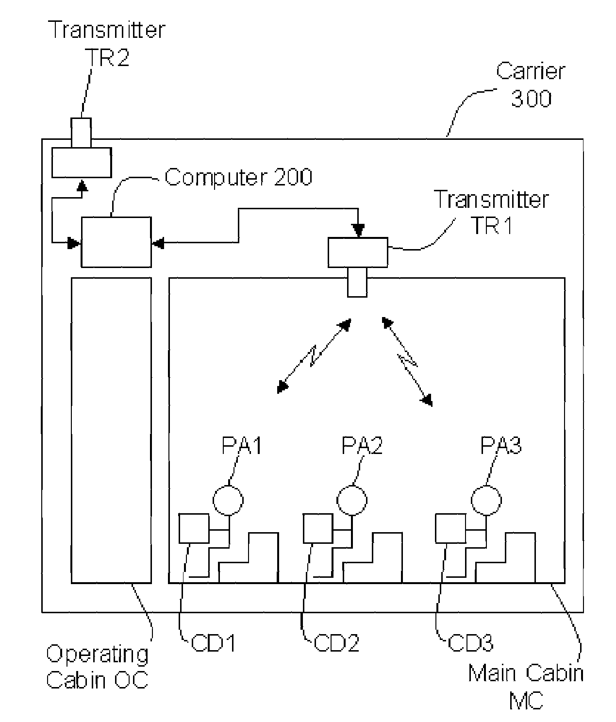
However, the foregoing prior arts do not disclose the transporation system which comprises the internal antenna system and the external antenna system which enable the passengers in the transporation system to implement wireless communication and enjoy satellite TV program shown in the cabin of the transporation system.

Method used


Image

  • Carrier
  • Carrier
  • Carrier

Examples


first embodiment

[0134]FIG. 13 illustrates the connection between Host H and Carrier 300. As described in the present drawing, Host H and Carrier 300 are connected via Network NT, such as the Internet and Base Station BS. The data sent from Host H is transferred to Network NT, which forwards the data to Base Station BS. Base Station BS transfers the data to Carrier 300 in a wireless fashion. The data sent from Carrier 300 is transferred to Base Station BS in a wireless fashion, which forwards the data to Network NT. Network NT transfers the data to Host H.

second embodiment

[0135]FIG. 14 illustrates the connection between Host H and Carrier 300. As described in the present drawing, Host H and Carrier 300 are connected directly. The data sent from Host H is transferred directly to Carrier 300 in a wireless fashion, and vice versa.

third embodiment

[0136]FIG. 15 illustrates the connection between Host H and Carrier 300. As described in the present drawing, Host H and Carrier 300 are connected via three artificial satellites, i.e., Artificial Satellite AS1, Artificial Satellite AS2, and Artificial Satellite AS3. The data sent from Host H is transferred to Artificial Satellite AS1 in a wireless fashion, which forwards the data to Artificial Satellite AS2 in a wireless fashion. Artificial Satellite AS2 forwards the data to Artificial Satellite AS3 in a wireless fashion. Artificial Satellite AS3 forwards the data to Carrier 300 in a wireless fashion. The data sent from Carrier 300 is transferred to Artificial Satellite AS3 in a wireless fashion, which forwards the data to Artificial Satellite AS2 in a wireless fashion. Artificial Satellite AS2 forwards the data to Artificial Satellite AS1 in a wireless fashion. Artificial Satellite AS1 forwards the data to Host H in a wireless fashion.

[0137]>

[0138]FIGS. 16 through 30 illustrate th...


PUM


Abstract

The transportation system, such a airplane, which comprises the cabin, the internal antenna system, and the external antenna system. The voice data and the non-voice data of a plurality of passengers located in the cabin are received via the internal antenna system and transferred via the external antenna system. The TV data received via the external antenna system is distributed in the cabin.

Description

CROSS REFERENCE TO RELATED APPLICATIONS[0001]This application claims the benefit of U.S. Provisional Application No. 60 / 481,871, filed 2004 / 01 / 08, which is hereby incorporated herein by reference in its entirety.BACKGROUND OF INVENTION[0002]The invention relates to navigation system and more particularly to that of airplanes, space shuttles, gliders, railway trains, buses, taxis, and all other types of carriers and transportation systems.[0003]U.S. Pat. No. 6,751,801 is introduced as a prior art of the present invention of which the summary is the following: ‘An aircraft in-flight entertainment system includes a satellite TV receiver, at least one video display connected to the receiver, and a multi-beam antenna on the aircraft for receiving signals from a plurality of satellite TV transponders. The multi-beam antenna may have right-hand circularly polarized (RHCP) and left-hand circularly polarized (LHCP) beams offset from one another by a beam offset angle. The beam offset angle m...

Claims


Application Information

Patent Timeline
Patent Type & Authority Patents(United States)
IPC IPC(8): H04B1/18
CPCH04B1/3822
Inventor FUJISAKI, IWAO
Owner CORYDORAS TECH
Learn More