Glass panel

a glass panel and glass technology, applied in the field of glass panels, can solve the problems of inability to maintain the compression void v, easy damage to the glass plate per se, and the inability to maintain the void, so as to prevent the si—o bond in the cracks, reduce the risk of glass damage, and prevent the effect of glass plate damag

Inactive Publication Date: 2006-10-03
NIPPON SHEET GLASS CO LTD
View PDF37 Cites 26 Cited by
  • Summary
  • Abstract
  • Description
  • Claims
  • Application Information

AI Technical Summary

Benefits of technology

[0011]Thus, since the tensile force remaining at the outer surfaces of the outer peripheries of the glass plates is reduced, with the decompression void V maintained in the decompressed condition, the stress concentrating on any flaws on the glass plate surfaces may be diminished. Further, even when an external force is applied to the glass plates, only a weak resultant is caused by a tensile force due to the external force and the residual tensile force, thereby to prevent cracks from generating in the glass plates.
[0039]With this construction, since the respective edge portions adjacent to the decompression void of both of the glass plates are chamfered by grinding, cracks are removed from the edge portions adjacent to the decompression void where a tensile stress and compressive stress, weak as they may be, are generated, as well as those in the edge portions exposed to the atmosphere where a strong tensile stress and compressive stress are generated. As a result, a glass panel strong against a load such as a wind pressure or impact is provided.

Problems solved by technology

As a result, the decompression void V cannot be maintained in the decompressed condition for a long period, and the glass plates 1 per se may easily be damaged.

Method used


Image

  • Glass panel
  • Glass panel
  • Glass panel

Examples


first embodiment

[First Embodiment]

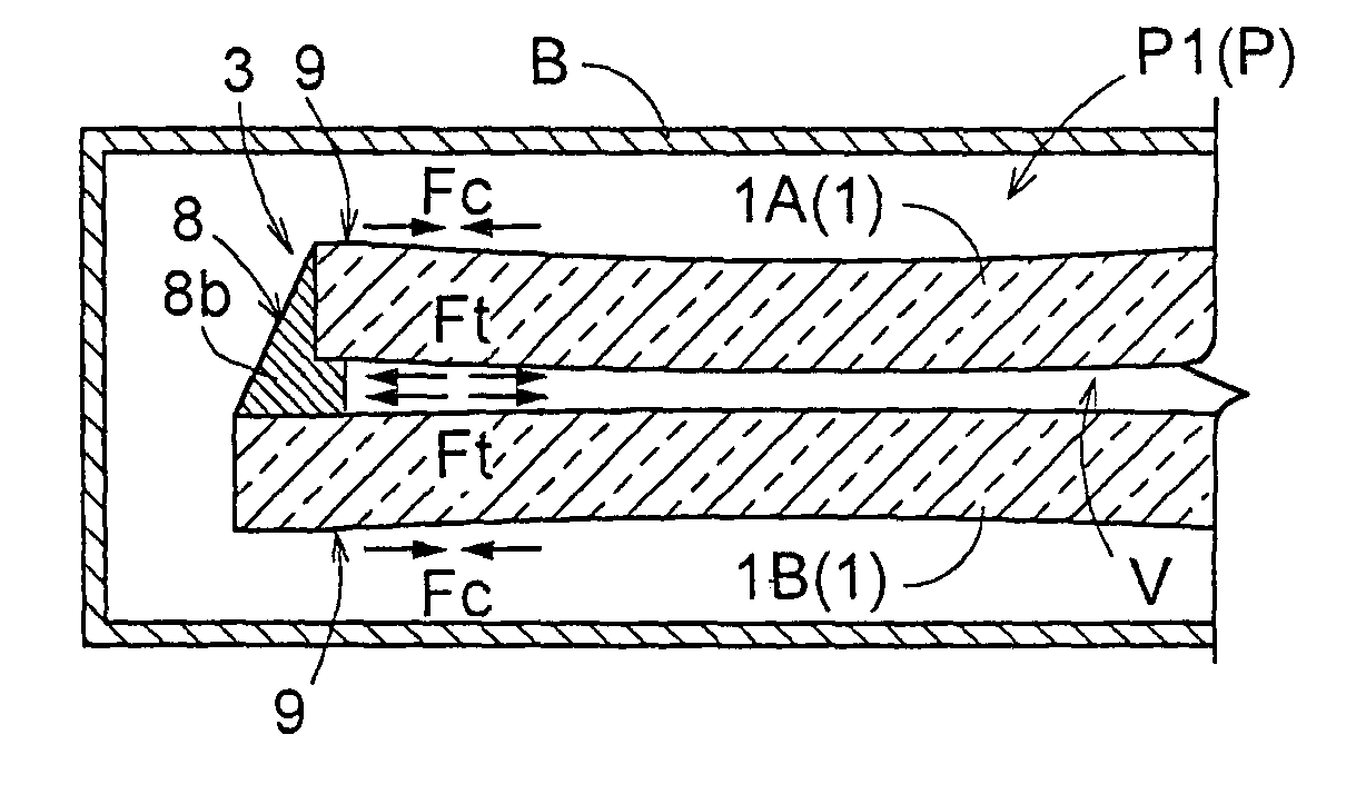
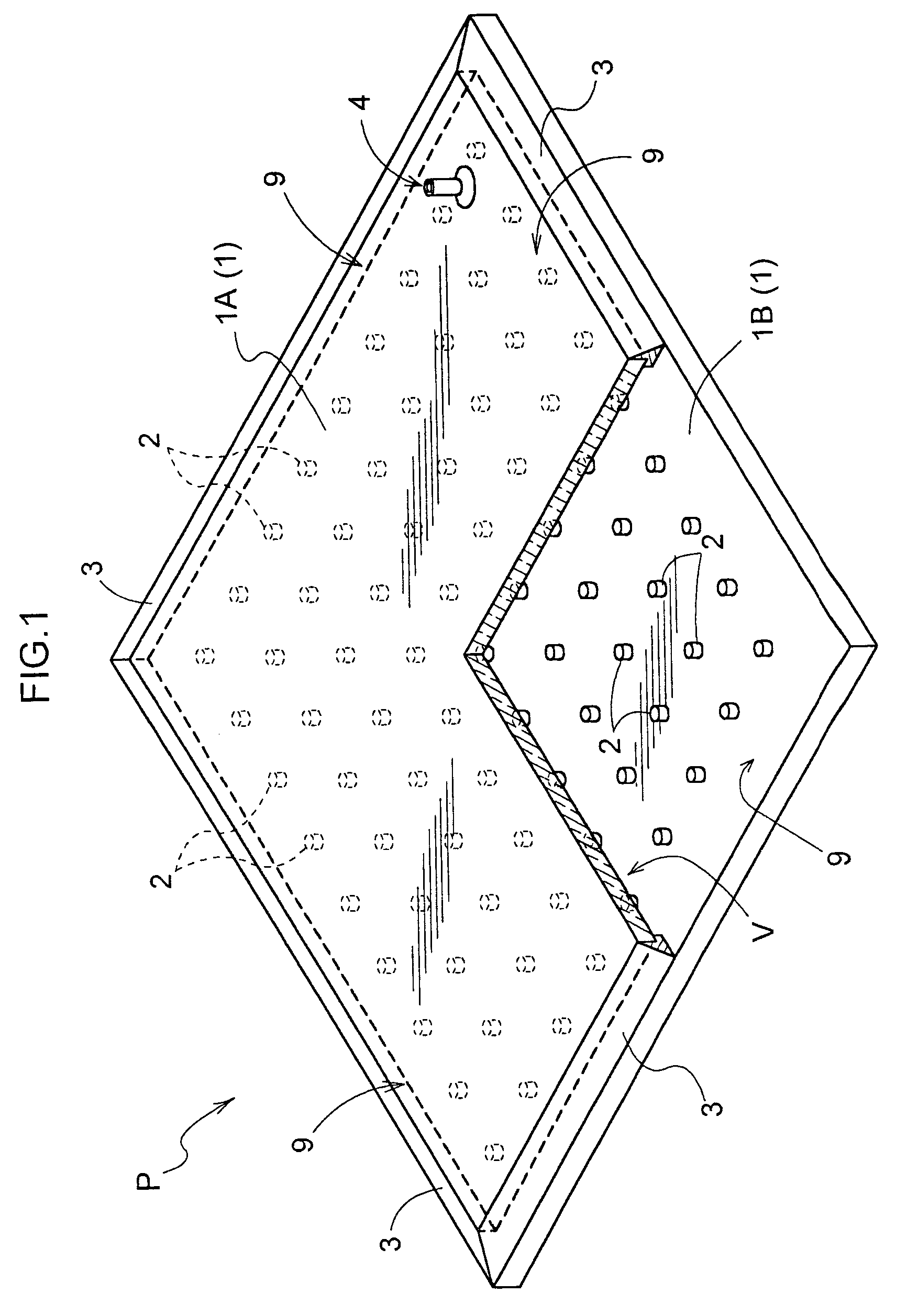
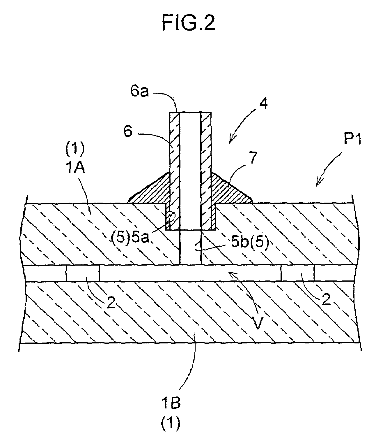
[0064]FIG. 1 shows a glass panel P in one embodiment of the present invention. The glass panel P comprises a pair of glass plates 1 (1A, 1B) opposed to each other, a plurality of spacers 2 disposed between the glass plates and spaced from each other along plate surfaces for maintaining a gap between the glass plates, and low melting point glass 3 such as solder glass of low gas permeability acting as a sealing member having a lower melting point than the glass plates 1 for sealing the glass plates 1 along the entire circumference at outer peripheries 9 thereof to define a decompression void V between the pair of glass plates 1A and 1B. At outer surfaces of the outer peripheries 9 adjacent where the glass plates 1A and 1B are sealed to each other through the low melting point glass (sealing member) 3 remains a compressive force Fc of approximately 0.5 to 4.0 MPa with the decompression void V being under at normal pressure (atmospheric pressure).

[0065]The glass plate...

second embodiment

[Second Embodiment]

[0084]It is possible to modify the glass panel P having the compression force Fe remaining at the outer surface of the outer peripheries of each glass plate 1A or 1B adjacent where the glass plates are sealed by the low melting point glass (sealing member) 3 with the decompression void V at atmospheric pressure. As illustrated in FIG. 6, the glass plates IA and 1B of the glass panel P may be arranged parallel or substantially parallel to each other across the decompression void V to be sealed with each other at the outer peripheries 9 thereof through the low melting point glass (sealing member) 3, allowing the compressive force Fc to remain at the outer surfaces of the outer peripheries 9 adjacent the sealed portions. To this end, it is effective to maintain the pair of glass plates IA and 1B in parallel by clipping the outer peripheries 9 of the plates at appropriate intervals, or to place a plate-like weight on the surface of the upper glass plate 1.A.

[0085]The ...

embodiment 1

[Alternative Embodiment 1]

[0088]In forming the glass panel P by arranging the pair of glass plates 1 cut by a cutter to be opposed to each other, the directions of cut portions have not been determined in use since this does not significantly affect the properties, e.g. a thermal insulation performance, of the glass panel P.

[0089]When the glass plates 1 are subjected to a load from the outside such as a wind pressure or impact, a bending moment acts on the glass plates 1. However, since the glass plates 1 are rigidly joined to each other at the outer peripheries 9 thereof by the sealing member, the two glass plates 1A and 1B combine to cope with the load as if a single glass plate. Therefore, a tensile stress occurs on the outer surfaces at the outer peripheries exposed to the atmosphere of one of the glass plates 1A, while a compressive stress occurs on the outer surfaces at the outer peripheries exposed to the atmosphere of the other glass plate 1B. In addition, a stress neutral a...


PUM

PropertyMeasurementUnit
pressureaaaaaaaaaa
pressureaaaaaaaaaa
stressaaaaaaaaaa

Abstract

A glass panel (P) comprising a pair of glass plates (1A, 1B) opposed to each other, spacers (2) disposed between the pair of glass plates for maintaining a gap therebetween, and a sealing member (3) having a lower melting point than the glass plates (1) for sealing the pair of glass plates (1A, 1B) at outer peripheries (9) thereof to form a decompression void (V) between the pair of glass plates (1A, 1B), wherein a compressive force Fc is allowed to remain at outer surfaces of the outer peripheries (9) of the glass plates (1), with the decompression void (V) being in atmospheric pressure condition.

Description

TECHNICAL FIELD[0001]The present invention relates to a glass panel comprising a pair of glass plates opposed to each other, spacers disposed between the pair of glass plates for maintaining a gap therebetween, and a sealing member having a lower melting point than the glass plates for sealing the pair of glass plates at outer peripheries thereof to define a decompression void between the pair of glass plates.BACKGROUND ART[0002]The above glass panel is intended to enhance a thermal insulation performance by maintaining the decompression void defined between the glass plates in a decompressed condition. In sealing the pair of glass plates at the outer peripheries thereof, the entire glass panel is heated to a predetermined temperature to melt the sealing member provided between the outer peripheries of the glass plates. The melted sealing member is then cooled and solidified, thereby to fix the glass plates to each other at the outer peripheries thereof.[0003]With the conventional g...

Claims


Application Information

Patent Timeline
Patent Type & Authority Patents(United States)
IPC IPC(8): E04C2/54C03C27/06C03C27/12E06B3/54E06B3/62E06B3/663
CPCC03C27/06E04B1/803E06B3/5454E06B3/6612E06B3/6617E06B3/6621E06B3/66304E06B3/66333E06B2003/6258Y02B80/12Y02B80/24Y02B80/10Y02B80/22Y02A30/242Y02A30/249
Inventor MINAAI, TETSUOMISONOU, MASAOFUTAGAMI, TORU
Owner NIPPON SHEET GLASS CO LTD
Why Eureka
Try Eureka