Window blind for a sliding roof system

a technology for sliding roofs and blinds, applied in the direction of windows, windscreens, superstructures, etc., can solve the problems of springs developing a comparably high frictional force, and achieve the effect of high frictional for

Active Publication Date: 2006-10-03
ROOF SYST GERMANY
View PDF5 Cites 33 Cited by
  • Summary
  • Abstract
  • Description
  • Claims
  • Application Information

AI Technical Summary

Benefits of technology

[0007]The pretensioning of the flat spiral spring causes the springs to develop a comparably high frictional force within the guide rail. This prevents the window blind from undesirably displacing on its own, eliminating the need to include a separate window blind brake to hold the window blind in a selected position.

Problems solved by technology

The pretensioning of the flat spiral spring causes the springs to develop a comparably high frictional force within the guide rail.

Method used


Image

  • Window blind for a sliding roof system
  • Window blind for a sliding roof system
  • Window blind for a sliding roof system

Examples


Embodiment Construction

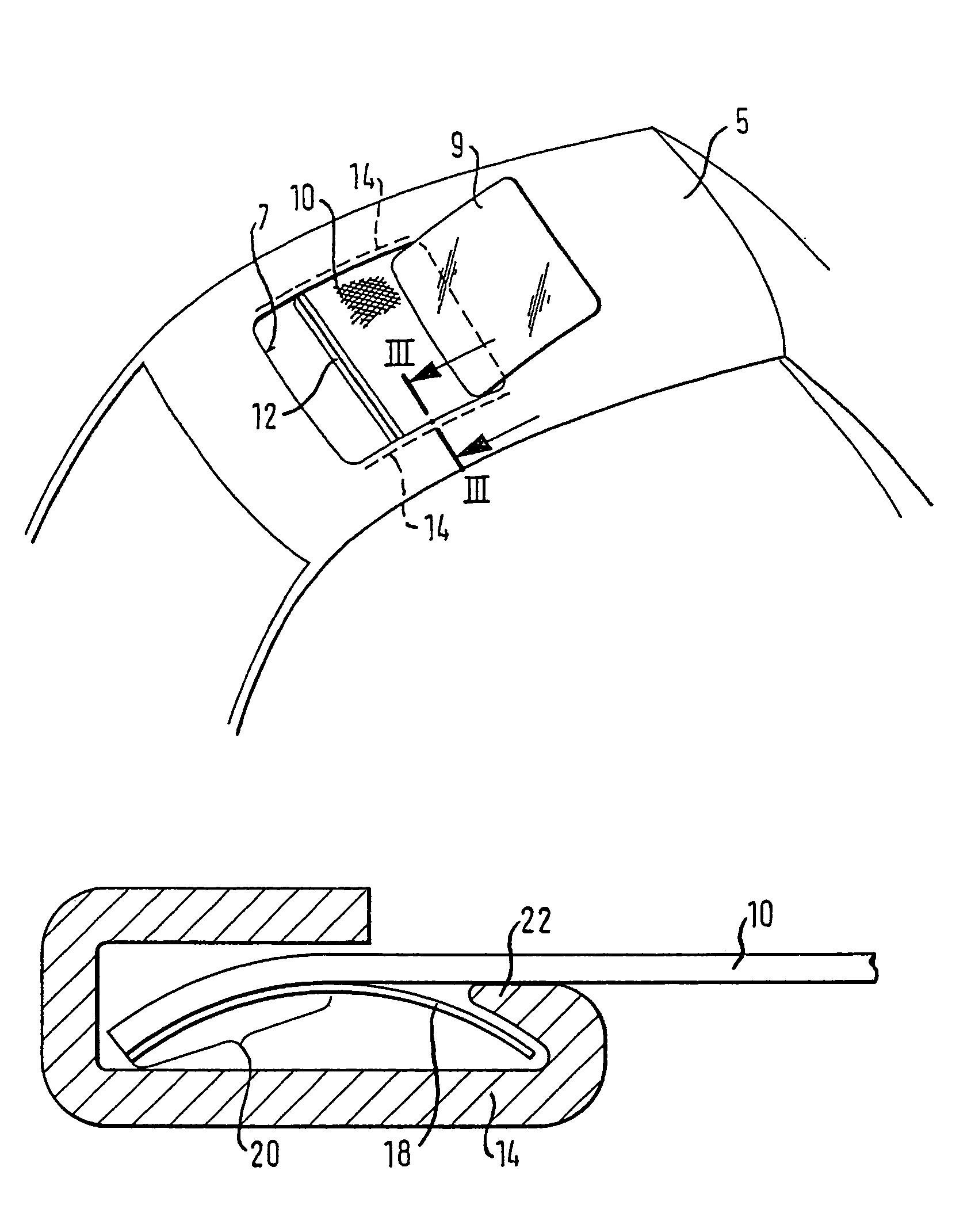
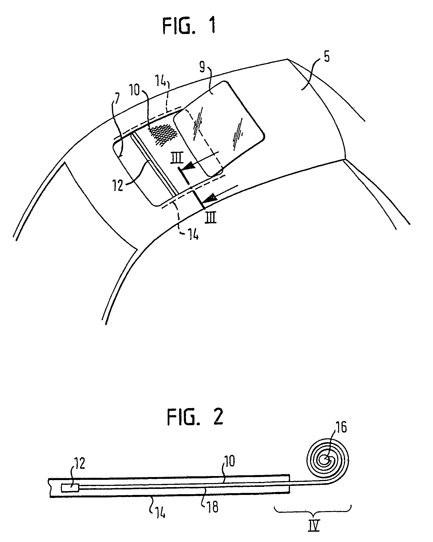
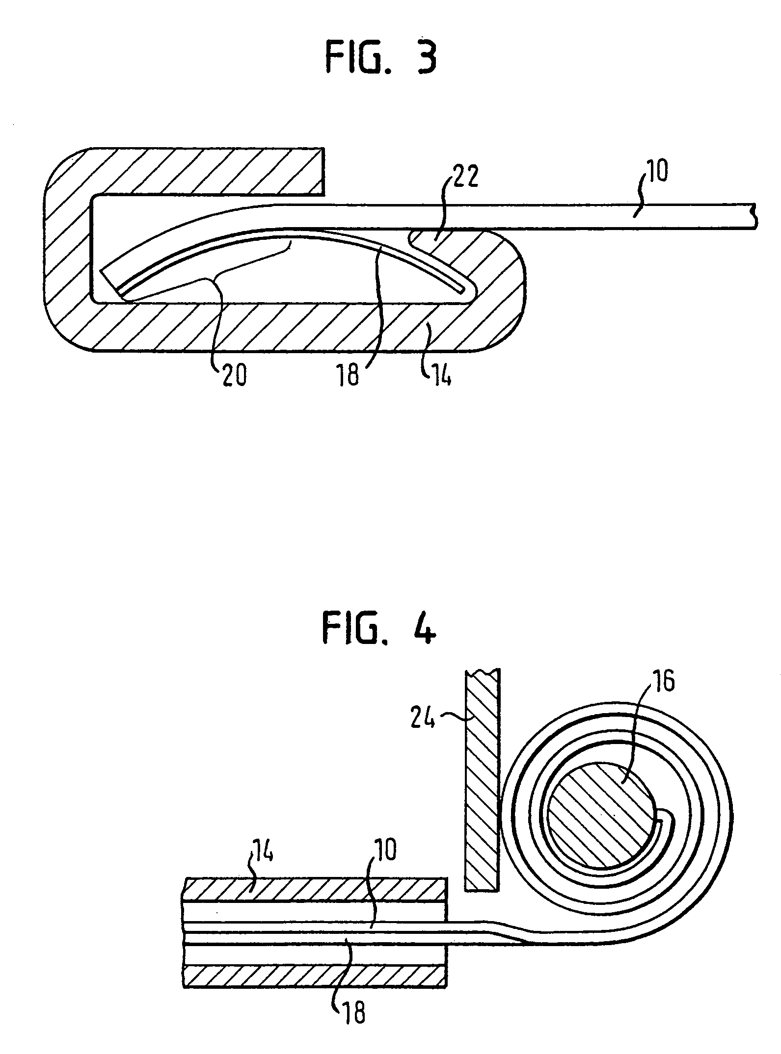
[0015]Generally, a window blind according to the present invention includes a flexible material and two flat spiral springs that extend along the longitudinal edges of the window blind. The flat spiral springs tend to contract into a spiral and act directly on the window blind itself instead of on a winding shaft. This ensures that the portions of the window blind that are not located in the guide rails will automatically be rolled into a coil. Thus, a very low tensile force acts on the portions of the window blind located in the guide rails. Moreover, the pretensioning of the flat spiral springs causes the springs to develop a comparably high friction within the guide rails, reliably preventing the window blind from displacing on its own and eliminating the need to include a separate window blind brake to hold the window blind in a desired position.

[0016]The flat spiral springs also allows the window blind to occupy a smaller installation space because spring biasing the winding sh...


PUM


Abstract

The invention relates to a window blind for a sliding roof system includes a flexible material and two flat spiral springs that extend along the longitudinal edges of the window blind. The flat spiral springs tend to contract into a spiral shape, winding the flexible material into a coil.

Description

REFERENCE TO RELATED APPLICATIONS[0001]The present invention claims the benefit of German Patent Application No. 102004017459.8, filed Apr. 8, 2004.TECHNICAL FIELD[0002]The invention relates to a window blind for a sliding roof system.BACKGROUND OF THE INVENTION[0003]A window blind for a sliding roof system may be attached underneath an opening in a vehicle roof to cover an opening in the vehicle roof to a greater or lesser extent according to the choice of the vehicle occupants. If the opening is to be exposed, the window blind is wound up on a winding shaft, which is biased by a spring in the wind-up direction of the shaft. The window blind can therefore be uncoiled against the biasing force of the spring to cover the opening. When the window blind lies underneath the opening in the vehicle roof, the window blind is prevented from sagging into the vehicle interior space by a guide rail on either side of the longitudinal edges of the window blind. Each guide rail receives a longitu...

Claims


Application Information

Patent Timeline
Patent Type & Authority Patents(United States)
IPC IPC(8): B60J1/20B60J7/00
CPCB60J7/00B60J7/0015
Inventor BECHER, THOMASBOEHM, HORSTGRIMM, RAINERBIEWER, CHRISTIAN
Owner ROOF SYST GERMANY
Why Eureka
Try Eureka