Connection device for signal wire

a connection device and signal wire technology, applied in the direction of contact members penetrating/cutting insulation/cable strands, electrical appliances, fastening/insulating connecting parts, etc., can solve the problems of inconvenient work, waste of working time and manual work, etc., to achieve the effect of reducing the disadvantage of the conventional connection devi

Inactive Publication Date: 2006-10-03
HUANG CHAO CHUN
View PDF9 Cites 14 Cited by
  • Summary
  • Abstract
  • Description
  • Claims
  • Application Information

AI Technical Summary

Benefits of technology

[0005]The present invention is to mitigate and / or obviate the disadvantage of the conventional connection device.
[0006]The primary objective of the present invention is to provide a connection device, wherein the first holding member and the second holding member are mounted on and removed from the signal wire by tightening or loosening the locking member, so that the connection device is attached to and detached from the signal wire easily and rapidly.
[0008]A further objective of the present invention is to provide a connection device, wherein the electrically conducting portion of the electrically conducting plate has a sword-headed shape so that the electrically conducting plate is inserted into the signal wire rapidly, thereby facilitating the user attaching the connection device to the signal wire.
[0009]A further objective of the present invention is to provide a connection device, wherein the two terminal units are connected with each other by a single electrically conducting plate without needing addition parts, thereby decreasing the cost of assembly and saving the manual work.

Problems solved by technology

However, the metal strip of the signal wire is secured to a metal plate by soldering so that it is difficult to mount the signal wire to the door or the window, thereby causing inconvenience to the worker and wasting the working time and manual work.

Method used


Image

  • Connection device for signal wire
  • Connection device for signal wire
  • Connection device for signal wire

Examples


Embodiment Construction

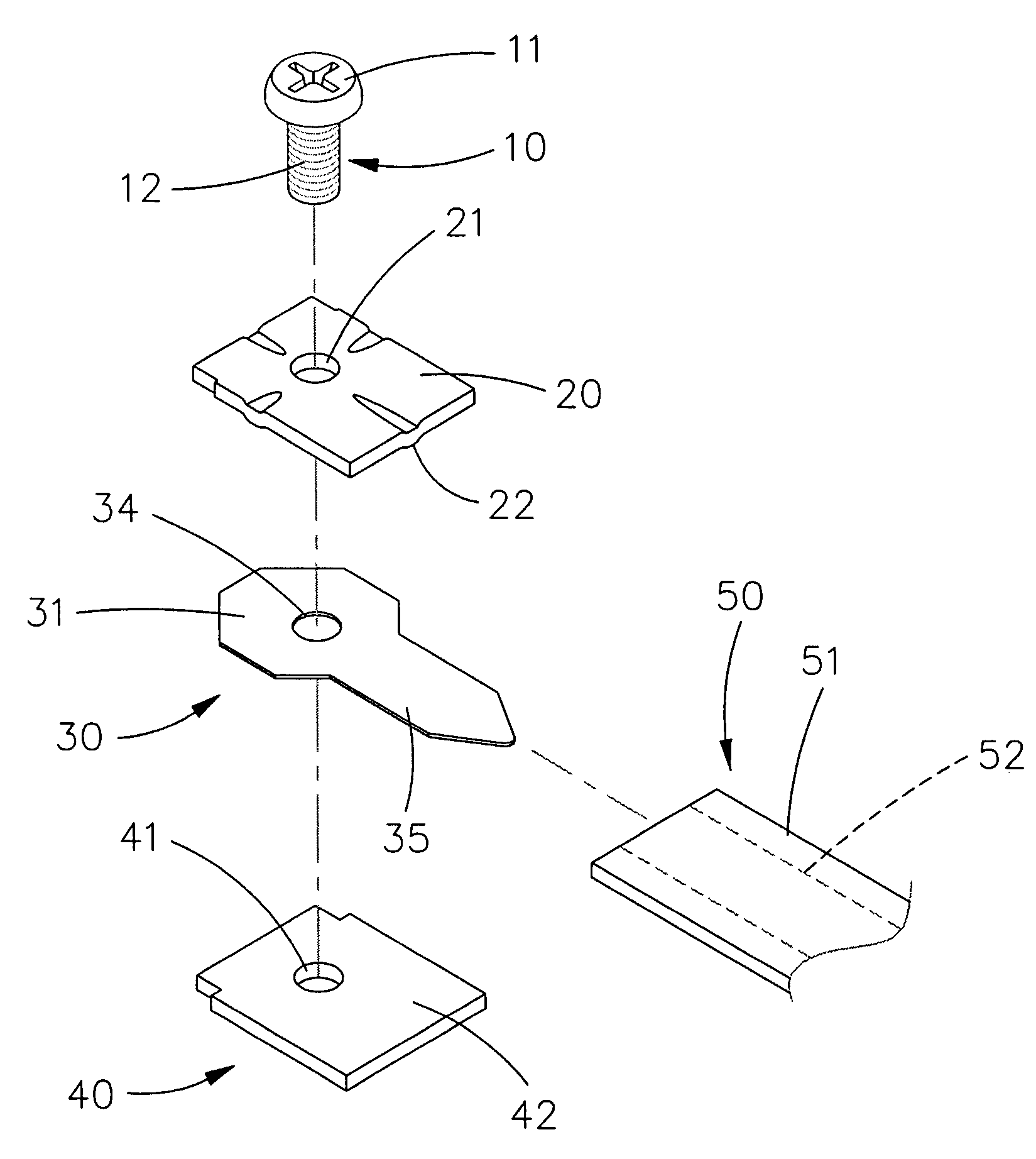
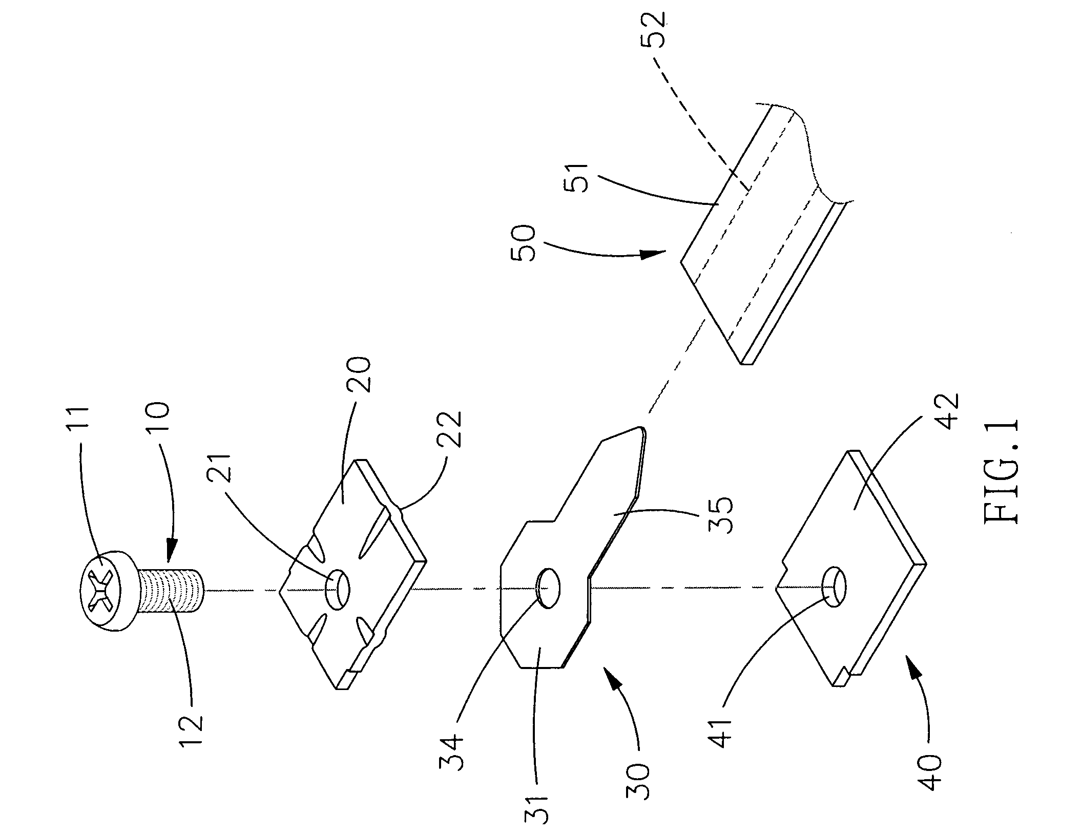
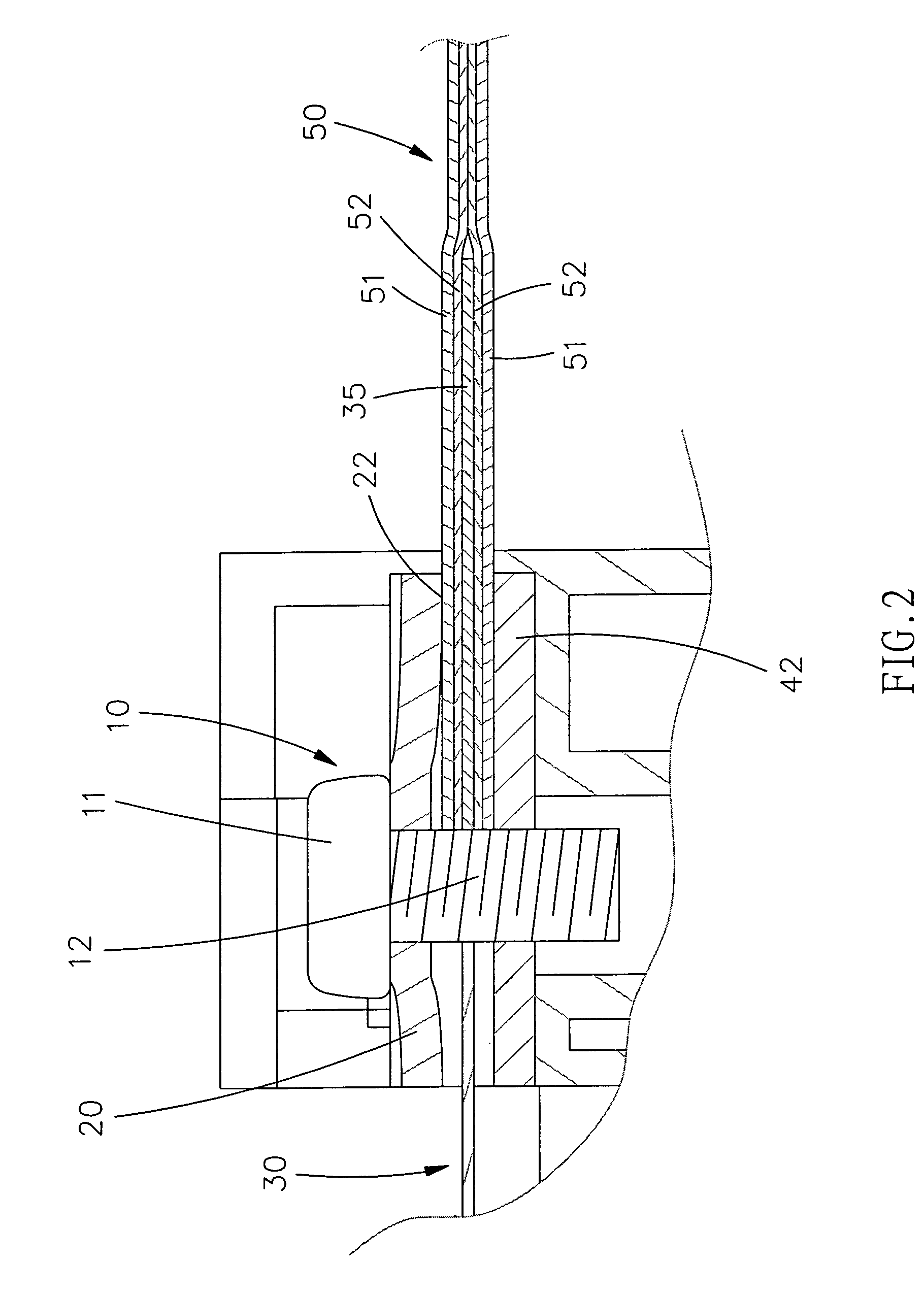
[0022]Referring to the drawings and initially to FIGS. 1–3, a connection device in accordance with the preferred embodiment of the present invention comprises at least one electrically conducting plate 30, at least one first holding member 20 mounted on a first side of the electrically conducting plate 30, at least one second holding member 40 mounted on a second side of the electrically conducting plate 30, and at least one locking member 10 extended through the first holding member 20, the electrically conducting plate 30 and the second holding member 40 to clamp the electrically conducting plate 30 between the first holding member 20 and the second holding member 40.

[0023]In the preferred embodiment of the present invention, the connection device comprises an electrically conducting plate 30, a first holding member 20 mounted on a first side of the electrically conducting plate 30, a second holding member 40 mounted on a second side of the electrically conducting plate 30, and a ...


PUM


Abstract

A connection device for a signal wire includes at least one electrically conducting plate, at least one first holding member mounted on a first side of the electrically conducting plate, at least one second holding member mounted on a second side of the electrically conducting plate, and at least one locking member extended through the first holding member, the electrically conducting plate and the second holding member to clamp the electrically conducting plate between the first holding member and the second holding member. Thus, the first holding member and the second holding member are mounted on and removed from the signal wire by tightening or loosening the locking member, so that the connection device is attached to and detached from the signal wire easily and rapidly.

Description

BACKGROUND OF THE INVENTION[0001]1. Field of the Invention[0002]The present invention relates to a connection device, and more particularly to a connection device for a signal wire.[0003]2. Description of the Related Art[0004]A signal wire is used for the anti-theft purpose. The signal wire includes an insulating layer, and a metal strip mounted in the insulating layer to transmit a signal. In assembly, the signal wire is secured to a determined place, such as the door, window or the like. In such a manner, a safety system supplies an electric power to the signal wire to detect an abnormal signal from the metal strip. Thus, when a person pulls the door or the window intentionally, the signal wire is broken, so that the metal strip is vibrated and produces an abnormal signal that is detected by the safety system which emits a warning signal to the security so as to achieve the anti-theft purpose. However, the metal strip of the signal wire is secured to a metal plate by soldering so ...

Claims


Application Information

Patent Timeline
Patent Type & Authority Patents(United States)
IPC IPC(8): H01R4/30H01R4/38
CPCH01R4/34H01R4/5033
Inventor HUANG, CHAO-CHUN
Owner HUANG CHAO CHUN
Why Eureka
Try Eureka