Dual-band bandpass filter

a filter and bandpass technology, applied in the field of dualband filters, can solve the problems of large area wasted, relative difficulty in the practical design and circuit layout stage, difficulty in the utility stage, etc., and achieve the effect of simple circuit layou

Active Publication Date: 2006-10-03
IND TECH RES INST
View PDF11 Cites 59 Cited by
  • Summary
  • Abstract
  • Description
  • Claims
  • Application Information

AI Technical Summary

Benefits of technology

[0008]It is therefore an object of the invention to provide a dual-band bandpass filter, which has a simple circuit layout in an extremely small area of a multilayer ceramic substrate, and can precisely produce two pass bands with two different center frequencies.

Problems solved by technology

However, the additional matching circuit required in this dual-band filter causes relative difficulty in the practical design and circuit layout stage.
However, to flexibly control the secondary resonance mode of step impedance half wavelength resonator, the impedance ration of the resonator might meet with the limitation of circuit implementation, thereby causing difficulty in the utility stage.
So, when the dual-band filter layout is to be performed on a multilayer board, a large area will be wasted and the specification of the general commercial components or modules cannot be satisfied.

Method used


Image

  • Dual-band bandpass filter
  • Dual-band bandpass filter
  • Dual-band bandpass filter

Examples


Embodiment Construction

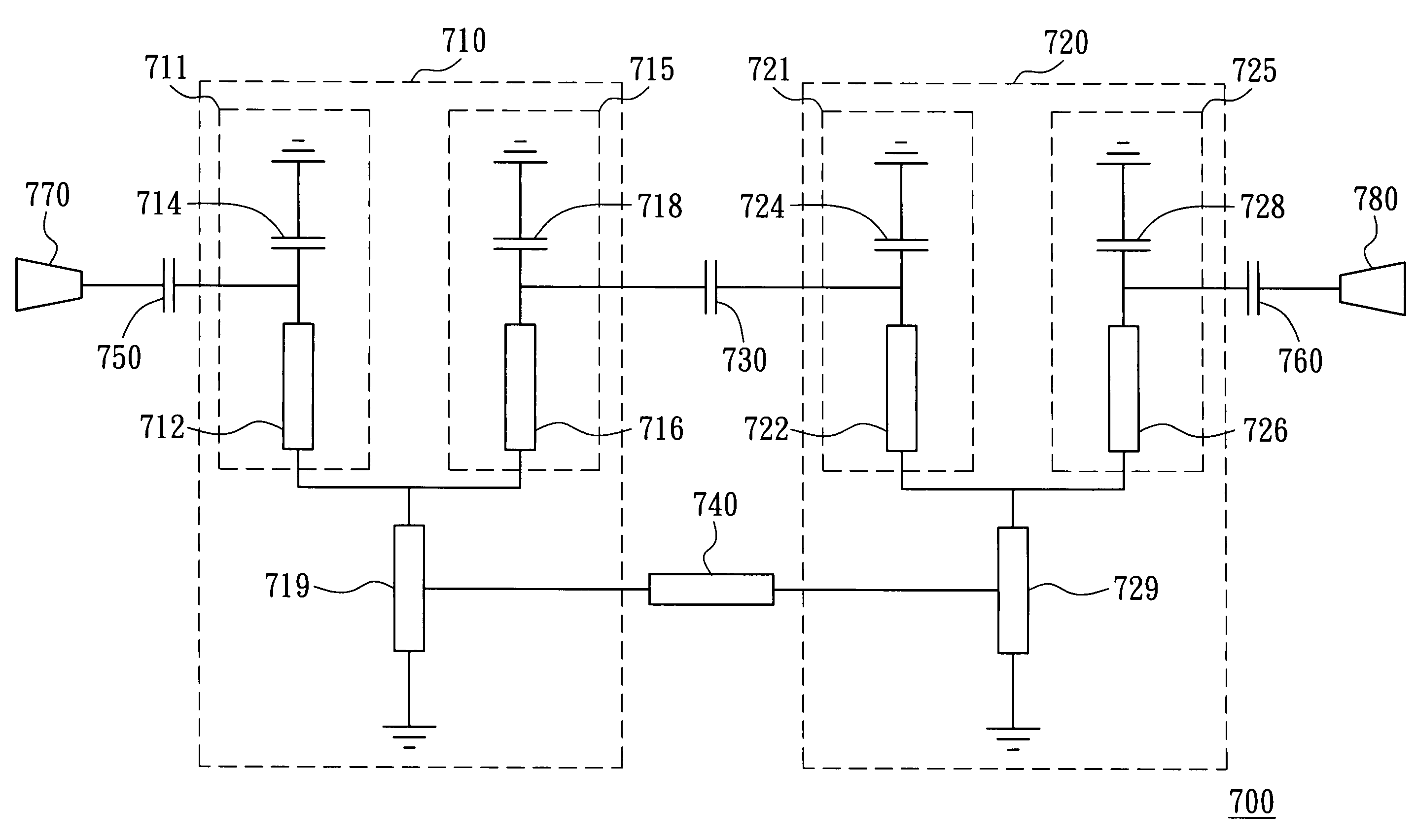
[0022]In a typical filter, a quarter-wavelength resonator is usually used to produce the resonance mode, wherein the length L of the transmission line of the resonator is about a quarter of the electromagnetic wavelength to be transmitted, and one end of the transmission line is grounded. If the physical length of the resonator is to be reduced, a grounding capacitor connected to the transmission line in series may be provided in order to shorten the transmission line without changing the resonance frequency of the resonator. FIG. 4 shows two independent resonators. The resonator 310 includes a transmission line 311 and a capacitor 313, both of which are connected in series. One end of the capacitor 313 is grounded, and one end of the transmission line 311 is also grounded. The resonator 320 includes a transmission line 321 and a capacitor 323, both of which are connected in series. One end of the capacitor 323 is grounded, and one end of the transmission line 321 is also grounded. ...


PUM


Abstract

A dual-band bandpass filter having a first pass band and a second pass band respectively corresponding to a first frequency and a second frequency. The filter includes a first pair of resonators, a second pair of resonators and a first coupling element. The first pair of resonators includes a first resonator and a second resonator, which share a first grounding transmission line and are grounded through the first grounding transmission line to generate coupling. The second pair of resonators includes a third resonator and a fourth resonator, which share a second grounding transmission line and are grounded through the second grounding transmission line to generate coupling. The first coupling element connected between the first and second pairs of resonators makes the first and second pairs of resonators produce coupling such that the dual-band bandpass filter has the first and second pass bands.

Description

[0001]This application claims the benefit of Taiwan application Ser. No. 93126436, filed Sep. 1, 2004, the subject matter of which is incorporated herein by reference.BACKGROUND OF THE INVENTION[0002]1. Field of the Invention[0003]The invention relates in general to a dual-band filter, and more particularly to a dual-band bandpass filter.[0004]2. Description of the Related Art[0005]The wireless local area network and mobile communication applications are growing wider and wider, and the development of the applications is advanced toward the multi-band multi-mode system. The dual-band bandpass filter is an important key component in a specific multi-band multi-mode radio frequency transceiver circuit. FIG. 1 shows the architecture of a concurrent dual-band receiver, which is proposed by Hossein Hashemi in “IEEE TRANSACTIONS ON MICROWAVE THEORY AND TECHNIQUES, VOL. 50, NO. 1, JANUARY 2002,” and entitled “Concurrent Multiband Low-Noise Amplifiers-Theory, Design, and Applications.”[0006...

Claims


Application Information

Patent Timeline
Patent Type & Authority Patents(United States)
IPC IPC(8): H01P5/12H01P1/20H01P3/08H01P7/08H04B1/00
CPCH04B1/0057H04B1/0067
Inventor CHEN, CHENG-CHUNG
Owner IND TECH RES INST
Why Eureka
Try Eureka