
Constant-current circuit capable of voltage compensation and zero-voltage switching

a constant-current circuit and zero-voltage switching technology, applied in the field of constant-current circuits, can solve the problems of inability to operate, burn leds, and excessive output current, and achieve the effect of effectively lowering the loss of power semiconductor elements and increasing power conversion efficiency

Inactive Publication Date: 2012-07-03
SKYNET ELECTRONICS
View PDF6 Cites 4 Cited by
  • Summary
  • Abstract
  • Description
  • Claims
  • Application Information

AI Technical Summary

Benefits of technology

[0019]In view of the aforementioned shortcomings of the commercially available constant-current circuits, the inventor of the present invention put years of practical experience into related research and experiments and finally succeeded in developing a constant-current circuit capable of voltage compensation and zero-voltage switching as disclosed herein. According to the present invention, not only can the output current generated by the constant-current circuit remain constant over a wide range of input voltage, but also the switching loss of power semiconductor elements is effectively lowered for the benefit of increasing power conversion efficiency.
[0020]It is an object of the present invention to provide a constant-current circuit capable of voltage compensation and zero-voltage switching, wherein the constant-current circuit is a single-switch isolated flyback converter and includes a control circuit, a sensing resistor, a transformer, a voltage divider, and a primary-side power switch. The control circuit obtains information related to a primary-side current of the transformer by way of the sensing resistor and obtains a compensation signal from an input voltage by way of the voltage divider, so as to control the primary-side power switch accordingly. Due to a compensating effect of the compensation signal, a peak voltage resulting from the sensing resistor is adjusted to a reference voltage through adding the compensation signal thereto, thereby enabling the constant-current circuit to generate a constant output current. According to the present invention, an extremely simple circuit layout with inexpensive electronic elements allows all the necessary information to be obtained from the primary side in the absence of any secondary constant-current detection circuits or feedback circuits. The primary-side power switch is controlled according to the information obtained, such that the output current generated by the constant-current circuit remains constant over a wide range of input voltage.
[0021]It is another object of the present invention to provide the foregoing constant-current circuit capable of voltage compensation and zero-voltage switching, wherein the control circuit uses a detection winding, which is wound on the primary side of the transformer but in phase with a secondary winding, to detect a voltage of the primary-side power switch or the primary-side current. When it is determined that the voltage of the primary-side power switch is zero, or when it is determined that the primary-side current is zero, the control circuit switches and turns on the primary-side power switch accordingly, thus substantially reducing the switching loss of the primary-side power switch that occurs at the instant when the primary-side power switch is turned on.

Problems solved by technology

By contrast, the unstable input voltage of a common driving circuit tends to cause unstable luminosity of LEDs or even generate an excessively high output current that may burn the LEDs.
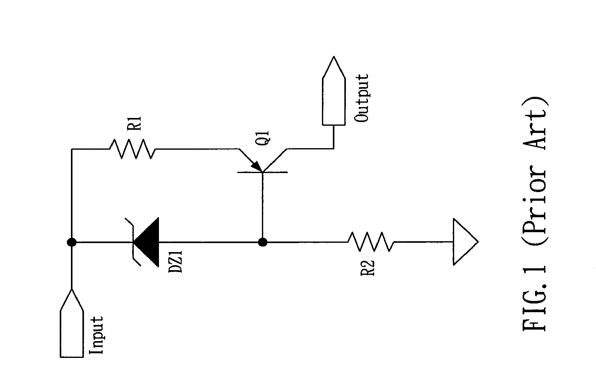
Although a constant-current circuit of this kind is advantageously simple in structure and incurs relatively low costs, it is disadvantaged by the fact that both the breakdown voltage VZener of the Zener diode DZ1 and the emitter-base voltage VEB(PNP) of the PNP transistor Q1 vary with temperature, and consequently the output current IO of the constant-current circuit is highly temperature-dependent.
Moreover, considerable power loss occurs when there is a large difference between the input voltage and the output voltage of the constant-current circuit, and as a result, the circuit's power utilization efficiency is lowered.
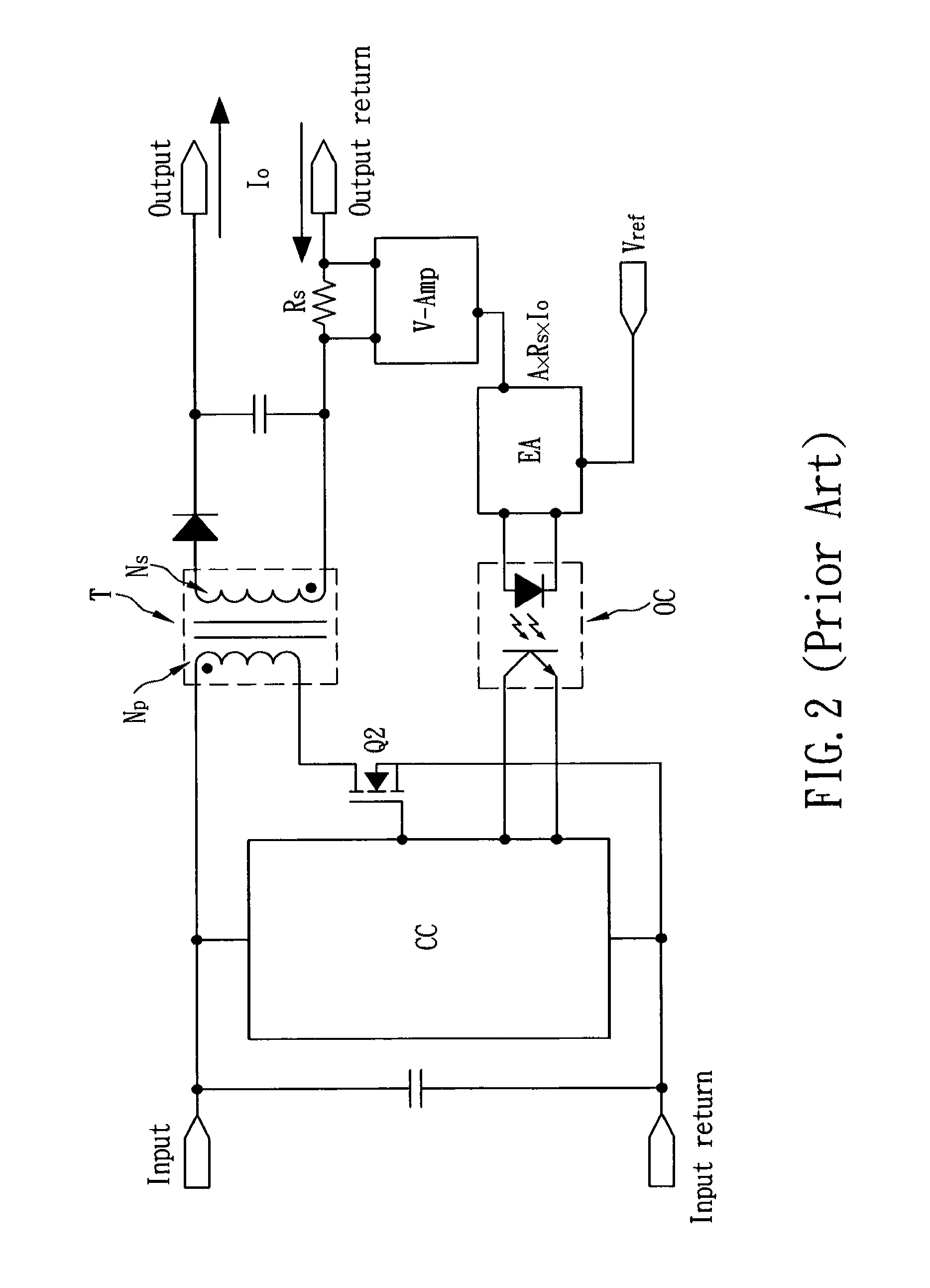
However, in spite of overcoming the drawbacks of the aforesaid simple constant-current circuit, the single-switch isolated flyback converter-based constant-current circuit has its own shortcomings, such as a complicated circuit structure and high costs.
Furthermore, as the control circuit CC relies on an optical coupling isolation element (i.e., the optical coupler OC) to transmit signals, the overall production costs and circuit layout complexity of the single-switch isolated flyback converter-based constant-current circuit are bound to be much higher than those of the aforesaid simple constant-current circuit.
However, the constant-current circuit in FIG. 3 still has its disadvantages.
Besides, as the control circuit CC causes constant-frequency DCM operation, the power switch Q3 must have certain switching loss.
Hence, when the constant-current circuit, of FIG. 3 is operated in constant-frequency DCM, a huge power loss takes place in the power switch Q3 at the instant when it is turned on, thus causing unnecessary waste of electric power.
When these constant-current circuits are operated in constant-frequency DCM, their power switches are all subject to heat generation and undue power loss upon being turned on.

Method used


Image

  • Constant-current circuit capable of voltage compensation and zero-voltage switching
  • Constant-current circuit capable of voltage compensation and zero-voltage switching
  • Constant-current circuit capable of voltage compensation and zero-voltage switching

Examples


Embodiment Construction

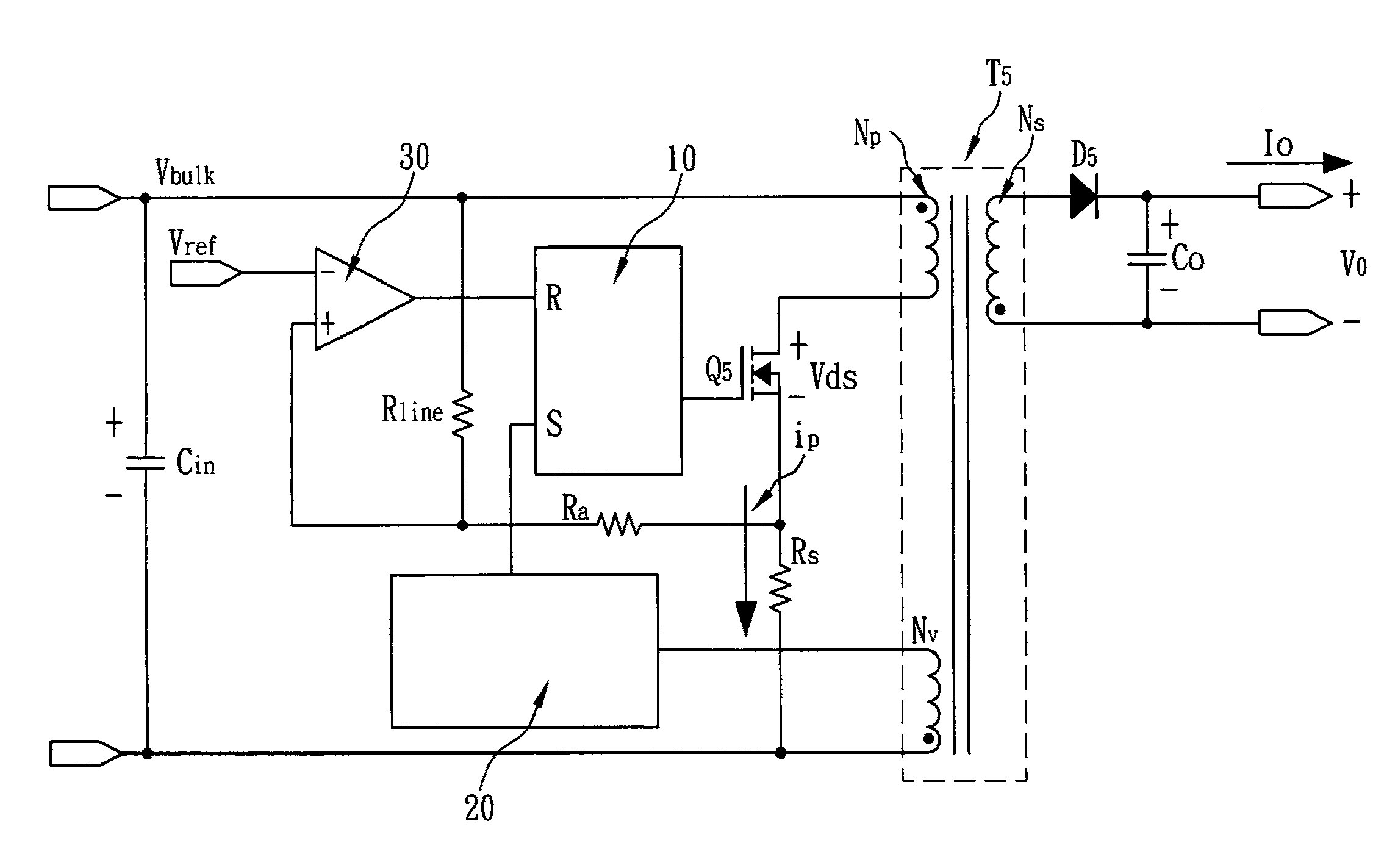
[0038]The present invention provides a constant-current circuit which is capable of voltage compensation as well as zero-voltage switching and is applicable to an LED-based lighting apparatus as an LED driving circuit whose output current stays constant. Referring to FIG. 9, the constant-current circuit is a single-switch isolated flyback converter operating in current mode and essentially includes a transformer T5, an input-voltage filter capacitor Cin, a linear resistor Rline, an auxiliary resistor Ra, an RS latch 10, a detection circuit 20, a comparator 30, a primary-side power switch Q5, a sensing resistor RS, a secondary-side power diode D5, and an output-voltage filter capacitor Co. The positive and negative electrodes of the input-voltage filter capacitor Cin are connected across the positive and negative ends of an input voltage Vbulk. The transformer T5 is operated in transition mode rather than constant-frequency DCM and includes a primary winding NP, a secondary winding N...


PUM


Abstract

The present invention is to provide a constant-current circuit capable of voltage compensation and zero-voltage switching, wherein the constant-current circuit is a single-switch isolated flyback converter and includes a control circuit, a sensing resistor, a transformer, a voltage divider, and a primary-side power switch. The control circuit obtains information related to a primary-side current of the transformer by way of the sensing resistor and obtains a compensation signal from an input voltage by way of the voltage divider, so as to control the primary-side power switch accordingly. Due to a compensating effect of the compensation signal, a peak voltage resulting from the sensing resistor is adjusted to a reference voltage through adding the compensation signal thereto, thereby enabling the constant-current circuit to generate a constant output current over a wide range of input voltage.

Description

FIELD OF THE INVENTION[0001]The present invention relates to a constant-current circuit, more particularly to a constant-current circuit capable of voltage compensation and zero-voltage switching, which utilizes a sensing resistor to obtain information related to a primary-side current of a transformer and utilizes a voltage divider to obtain a compensation signal from an input voltage, so as to control a primary-side power switch for adjusting a peak voltage resulting from the sensing resistor to a reference voltage through adding the compensation signal thereto, thereby enabling the constant-current circuit to generate a constant output current.BACKGROUND OF THE INVENTION[0002]Recently, as energy saving and carbon dioxide reduction have become a global campaign, and with the awareness of environmental protection on the rise, there is a trend to replace lighting apparatuses using the traditional incandescent or fluorescent lamps with those using light-emitting diodes (LEDs), which ...

Claims


Application Information

Patent Timeline
Patent Type & Authority Patents(United States)
IPC IPC(8): H02M3/335
CPCH02M3/33523
Inventor LIANG, JIM-HUNG
Owner SKYNET ELECTRONICS
Learn More