
Illuminated keyboard and control method thereof

Active Publication Date: 2021-09-30
ANAPEX TECH
View PDF0 Cites 1 Cited by
  • Summary
  • Abstract
  • Description
  • Claims
  • Application Information

AI Technical Summary

Benefits of technology

The present invention aims to solve the problem of high manufacturing costs associated with complex circuit layout of conventional illuminated keyboards. The circuit layout of the present invention requires a single-layer circuit board and a hardware only needs to be additionally provided with the feedback line in coordination with a signal detection manner. This results in a simple and convenient line architecture for the illuminated keyboard. Additionally, the feedback terminals need to be added in addition to the input terminals and the output terminals of the light-emitting diode modules to achieve the purpose of controlling the production cost. In summary, the present invention provides a cost-effective solution for illuminated keyboards.

Problems solved by technology

The former is high in cost due to more layer numbers of the circuit boards, and the latter with the single-layer circuit board also has the problem of high cost due to relatively complex circuit layout.

Method used


Image

  • Illuminated keyboard and control method thereof
  • Illuminated keyboard and control method thereof
  • Illuminated keyboard and control method thereof

Examples


Embodiment Construction

[0014]The detailed description and technical content of the present invention are described below with reference to the accompanying drawings.

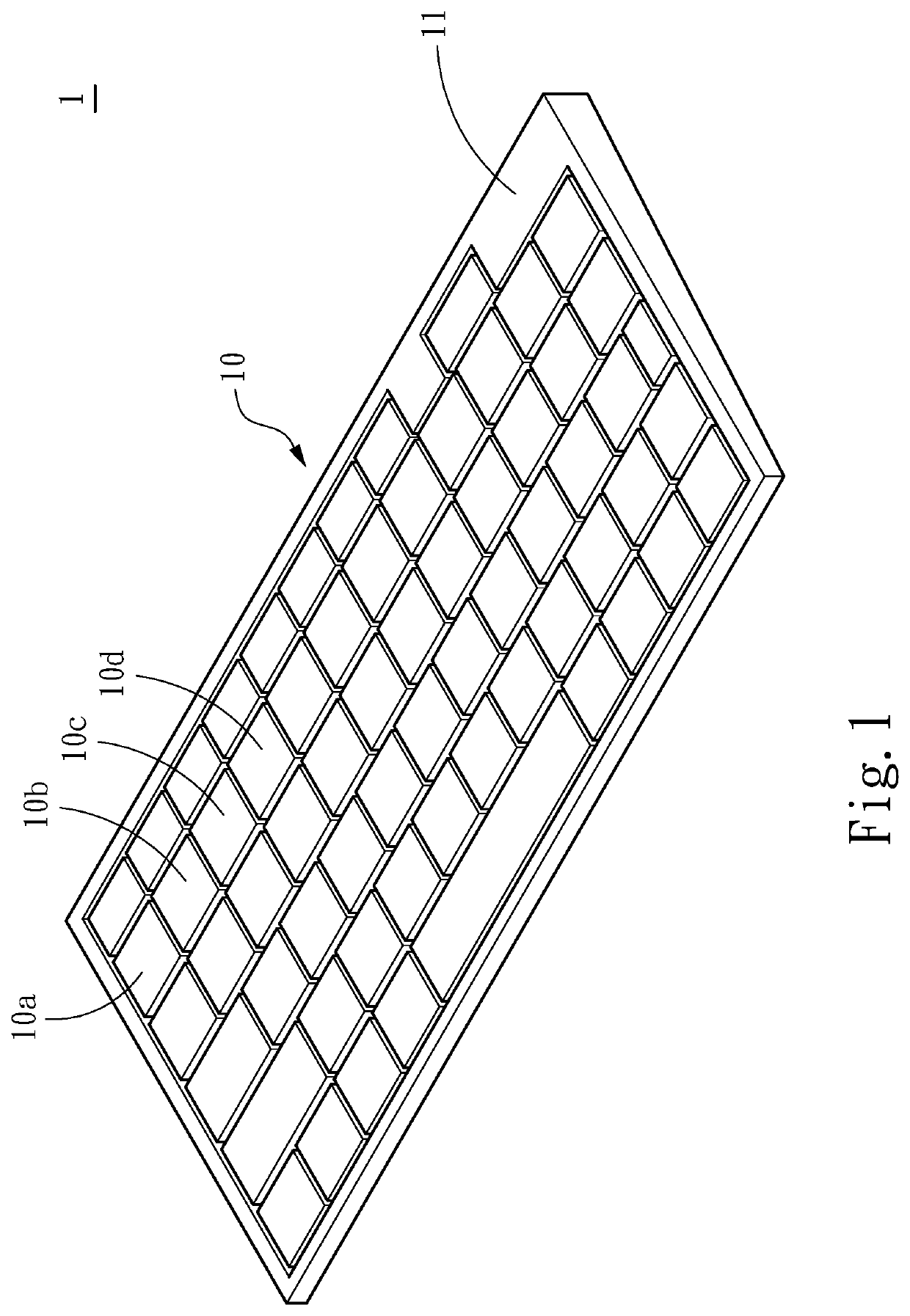
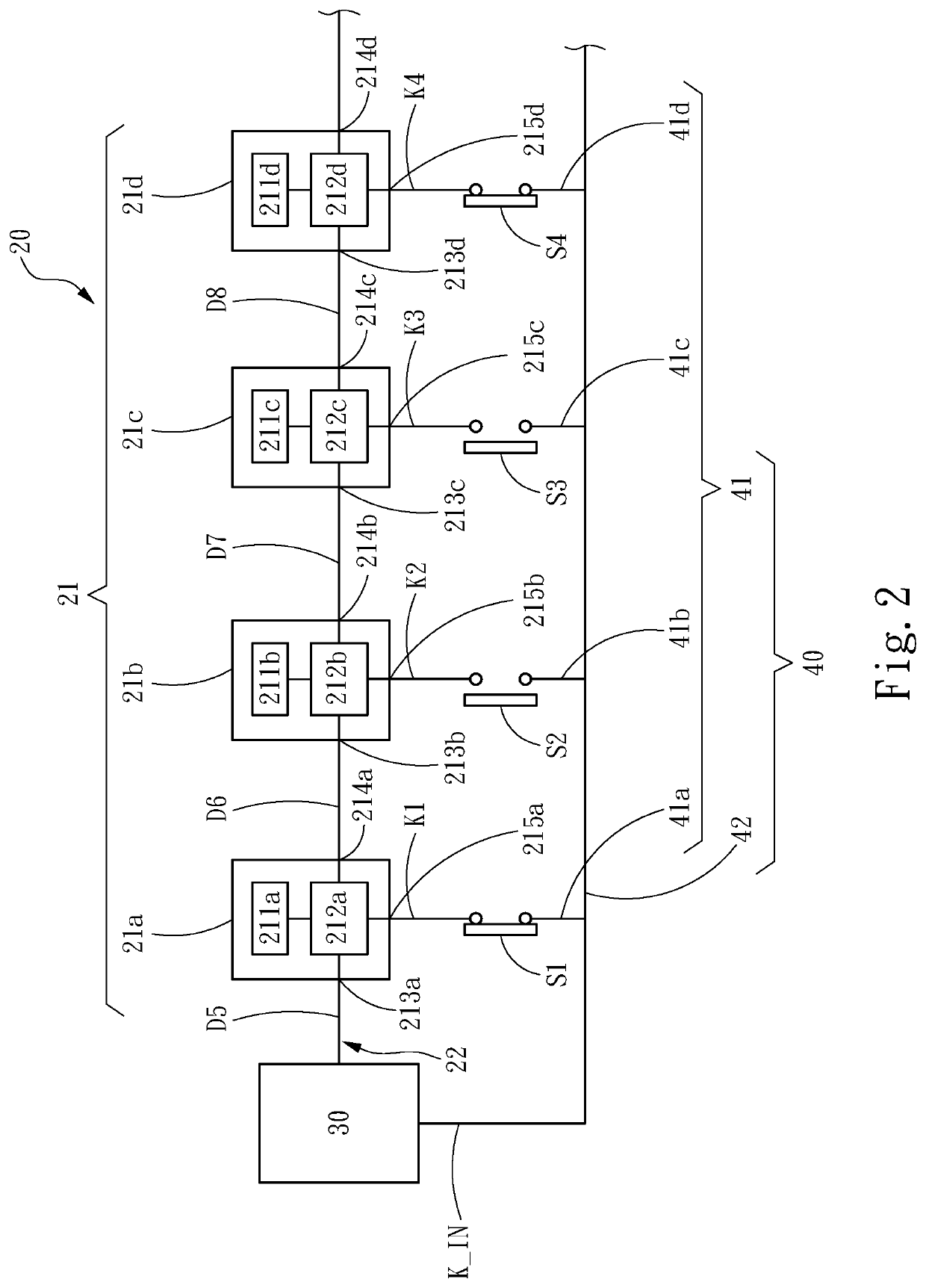
[0015]Referring to FIG. 1 and FIG. 2 which are a three-dimensional outside diagram and a diagram of the circuit architecture of one embodiment of the present invention respectively, the embodiment of the present invention discloses an illuminated keyboard 1 including a plurality of keys 10, a light-emitting diode light string 20, a controller 30 and a feedback line 40. The keys 10 are installed on a base 11, and the light-emitting diode light string 20, the controller 30 and the feedback line 40 are also arranged on the base 11. The preceding descriptions are intended to be illustrative, and these elements may also adopt other assembly manners according to the actual use and the manufacturing demands.

[0016]As shown in FIG. 2, the light-emitting diode light string 20 includes a plurality of light-emitting diode modules 21 which are connected wi...


PUM


Abstract

An illuminated keyboard includes a light-emitting diode light string, a controller, a feedback line and a plurality of keys. The light-emitting diode light string includes a plurality of light-emitting diode modules which are connected in series through a serial connection wire. Each light-emitting diode module includes a light-emitting diode chip and a drive circuit. The controller is electrically connected with the light-emitting diode light string. The feedback line is electrically connected between the light-emitting diode modules and the controller. The keys correspond to the light-emitting diode modules and are electrically connected with the feedback line. Each light-emitting diode module emits light according to a received light-emitting signal and outputs a feedback signal. When at least one of the keys is switched to a pressing state, the feedback signal is pulled from a first level to a second level for the controller to differentiate the key in the pressing state.

Description

FIELD OF THE INVENTION[0001]The present invention relates to an illuminated keyboard and a control method thereof, in particular to an illuminated keyboard with light-emitting diodes connected in series through a single wire and a control method for the illuminated keyboard.BACKGROUND OF THE INVENTION[0002]Based on the demands of consumers, more and more keyboards are configured with a light emitting function, wherein some keyboards are for decorative purposes, and some keyboards aim at providing a function of illumination or prompt. With changes of the market trend, the proportion of the illuminated keyboards (or backlight keyboards) in the keyboard market rises gradually, and the illuminated keyboards even become one of standard accessories of computers.[0003]Conventional illuminated keyboards can be found in R.O.C. Utility Model Patent No. M482920, which discloses a flexible circuit board applied to a keyboard backlight module, the flexible circuit board includes a backlight modu...

Claims


Application Information

Patent Timeline
IPC IPC(8): H01H13/83H01H9/16G06F1/16G06F3/02
CPCH01H13/83H01H9/161H01H2009/164G06F3/0202G06F1/1662H01H9/167H01H2239/01H01H2219/039H01H2219/04H01H13/704
Inventor HUANG, TSUNG-WEN
Owner ANAPEX TECH
Learn More