Industrial controller based on distributable technology objects

a technology object and industrial controller technology, applied in the direction of program control, total factory control, instruments, etc., can solve the problem of limited expansion

Inactive Publication Date: 2006-10-03
SIEMENS AG
View PDF25 Cites 18 Cited by
  • Summary
  • Abstract
  • Description
  • Claims
  • Application Information

AI Technical Summary

Benefits of technology

[0007]Therefore, an object of the present invention is to create optimal features of an industrial controller with regard to its control structure, as well as its functionality, for different control tasks, different boundary conditions and requirements of the underlying technical processes in a simple manner.
[0008]The inventors have based this on the finding that the run time system and / or engineering system of the industrial controller uses both programmable controller functionality as well as motion and / or technology functionality. The opportunity for dynamic loading of function code into the run time system and / or the engineering system of the industrial controller, (i.e., scaling of the controller) permits the design and development of the controller to be facilitated by a separation of technological functionality and device functionality.

Problems solved by technology

This expandability is limited only by hardware restrictions (e.g., CPU, power or memory restrictions).

Method used


Image

  • Industrial controller based on distributable technology objects
  • Industrial controller based on distributable technology objects
  • Industrial controller based on distributable technology objects

Examples


Embodiment Construction

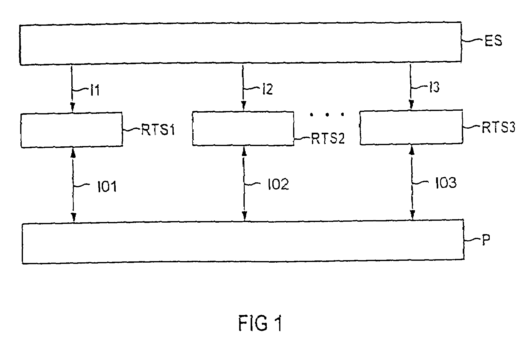
[0050]FIG. 1 uses a block diagram to show that a technical process P may be controlled over at least one run time system RTS1–RTS3 of an industrial controller. The connection between the run time systems RTS1–RTS3 of the controller and the technical process P is bidirectional over inputs / outputs IO1–IO3. The controller is programmed and, thus, the performance of the run time systems RTS1–RTS3 is stipulated in the engineering system ES. Engineering system ES contains tools for configuration, design and programming for machines and for controllers of technical processes. Programs generated in the engineering system ES are transmitted over information paths I1–I3 to the run time systems RTS1–RTS3 of the controllers. The three dots between RTS2 and RTS3 indicate that additional controllers and run time systems may be present. With regard to its hardware equipment, an engineering system ES may comprise a computer system with a graphic display screen (e.g., a display), input means (e.g., ...


PUM


Abstract

The loadability of technology object types into a run time system of an industrial controller permits functional expansion of the basic system of the controller as well as technological scaling of the controller. The loaded technology object types are instantiable, and may be distributed, as needed. Technology object types may be loaded in the form of technology packages and a user may use the functionality of the invention directly in a user program with a separation between technological functionality and device functionality.

Description

FIELD OF THE INVENTION[0001]The present invention relates to an industrial controller for technical processes, in particular for production machines.[0002]Furthermore, the present invention relates to a method of programming and designing industrial controllers for technical processes, in particular for production machines.BACKGROUND[0003]An industrial controller may be a separate device or it may be integrated into a computer, a PC, a stand-alone unit or a drive.[0004]Prior industrial controllers for automation of technical processes have been based essentially either on a programmable controller functionality, a motion control (“MC”) functionality or a technology functionality. Since a certain scope of function is stipulated as part of such functionalities, optimal adaptation to the requirements of a special process is limited. An entire group of functions is often superfluous in a specific application (e.g., when using an MC controller for machine tools, any functionality that mi...

Claims


Application Information

Patent Timeline
Patent Type & Authority Patents(United States)
IPC IPC(8): G05B15/00G06F9/44B62K15/00G05B19/042G05B19/418
CPCB62K15/00G05B19/0426G05B19/41865G05B2219/23255G05B2219/23262Y02P90/02
Inventor HORN, WOLFGANGACKERMANN, THOMASBIRZER, JOHANNES
Owner SIEMENS AG
Why Eureka
Try Eureka