
Method for simulating the deposition of a sedimentary sequence in a basin

a sedimentary sequence and basin technology, applied in the field of simulating the deposition of sedimentary sequences in basins, can solve the problems of not ensuring a satisfactory agreement between the results of the model and what is observed, and never succeeding

Active Publication Date: 2006-10-03
INST FR DU PETROLE
View PDF4 Cites 26 Cited by
  • Summary
  • Abstract
  • Description
  • Claims
  • Application Information

AI Technical Summary

Problems solved by technology

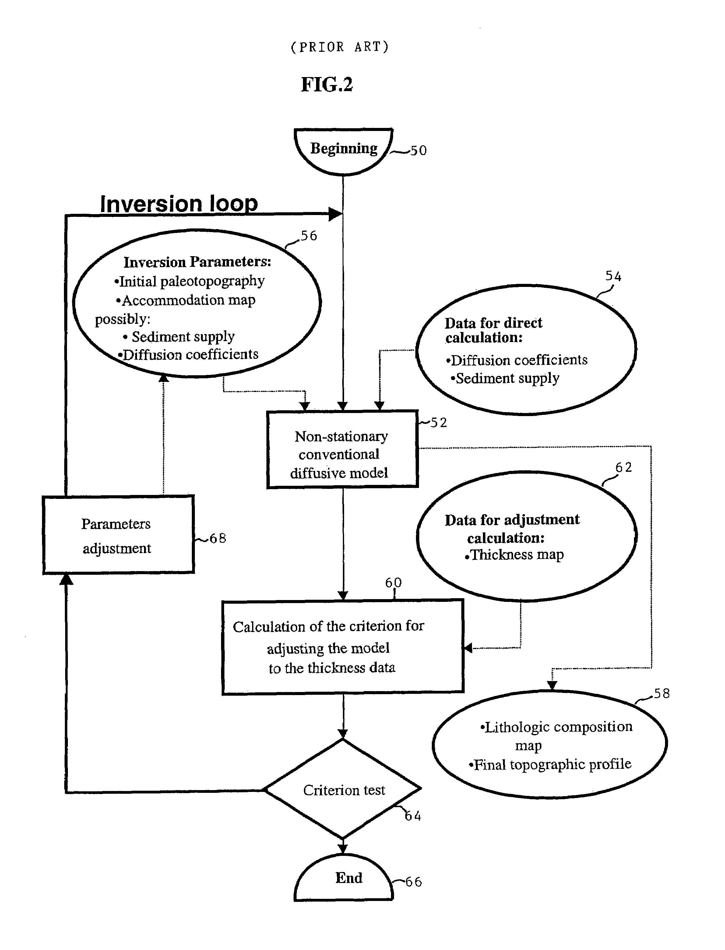
However, although it allows improving the agreement between what is observed and the model obtained, the inversion procedure does not ensure a satisfactory agreement between the result of the model and what is observed.
This also applies to an automatic procedure: it can never succeed if the data initially proposed by the user are too far from the solution.

Method used


Image

  • Method for simulating the deposition of a sedimentary sequence in a basin
  • Method for simulating the deposition of a sedimentary sequence in a basin
  • Method for simulating the deposition of a sedimentary sequence in a basin

Examples


application example

[0089]The following example applies to an Oman sedimentary basin. The medium is assumed to be cylindrical here, that is it remains unchanged in the direction perpendicular to the figures shown. This case i s therefore a 2 D c ase, that is simplified in relation to the 3D general case to which the method applies. The data used come from a seismic line shown in FIG. 4. It is a vertical (Depth) section of the basin along the y axis. The sequence to which the method applies is shown in this figure: it is defined by its upper and lower boundaries (referred to as “top” of the sequence” by a continued line and “base of the sequence” by a doted line respectively).

[0090]The spatial distribution of the sequence thicknesses is shown in FIG. 5 with the horizontal distance X in meters along the x axis and the vertical thickness in meters along the y axis. The method described above was applied in the monolithologic case, for different selections of diffusion coefficients in the marine environmen...


PUM


Abstract

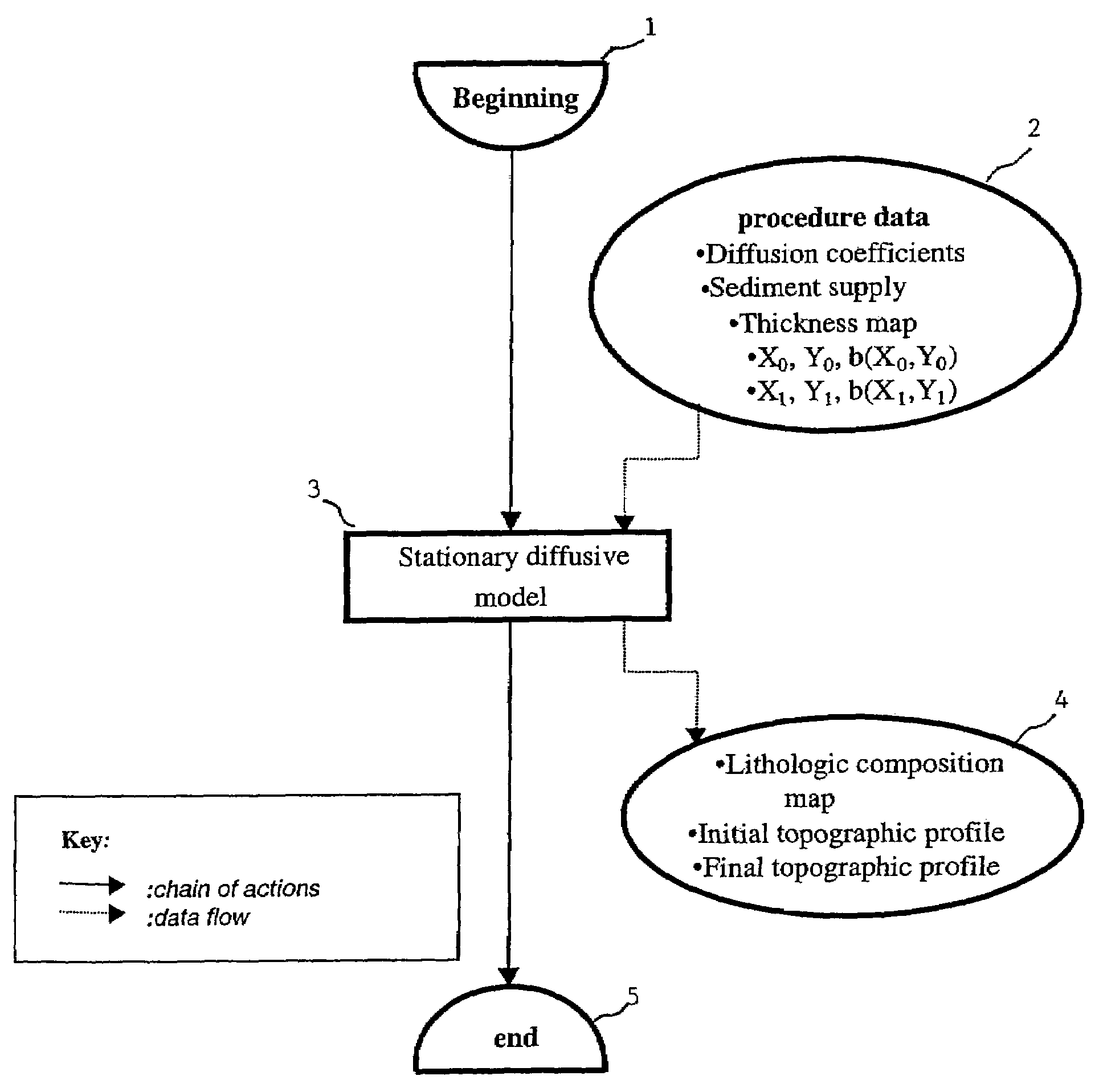
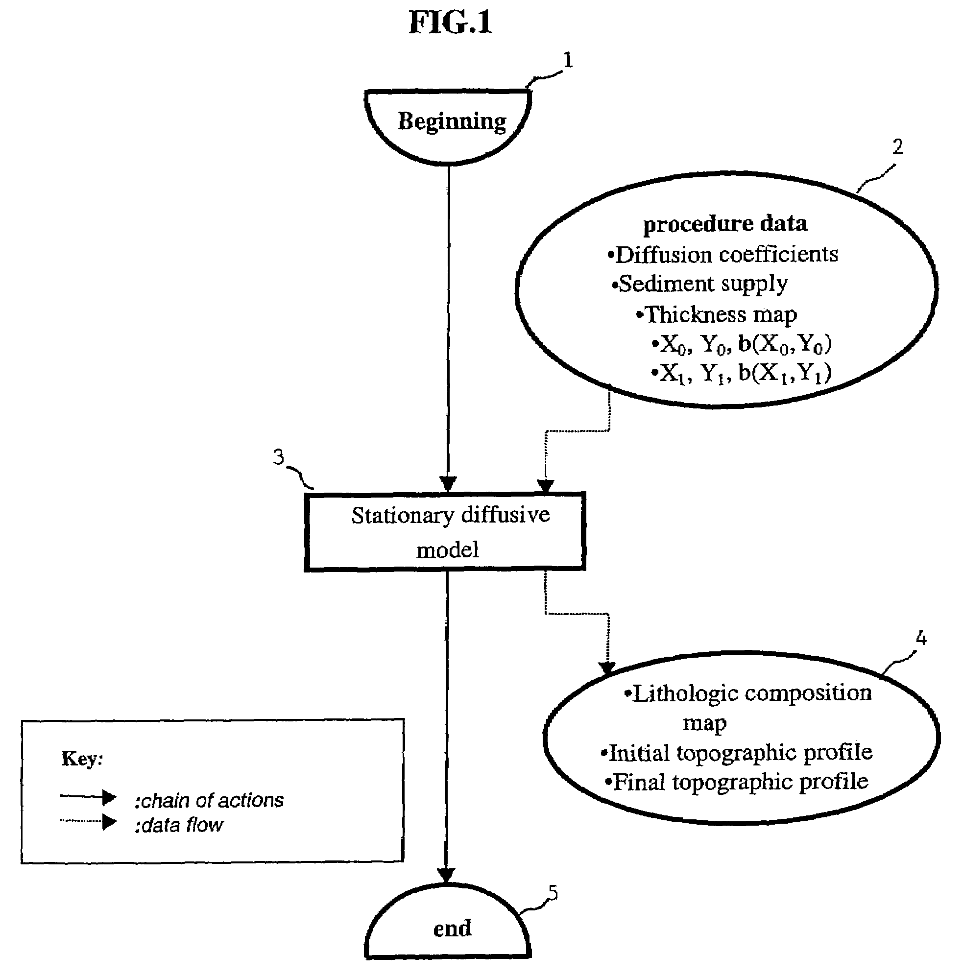
The invention is a method relating to the formation by simulation of a reference map of the spatial distribution of the sediment supply, according to the composition thereof, in a sedimentary basin during a sedimentary deposition sequence (during a given geologic time interval) and also allows obtaining the topography of the land surface of the basin at the beginning and at the end of this period. The available input data are a map of the thickness of the sedimentary layer studied, known by interpretation of seismic survey results, data relative to the location and to the composition of the sediment supply at the boundaries of the sedimentary basin being studied, obtained by interpretation of seismic surveys, measurements and observations, and physical parameters characterizing transportation of the sediments (diffusion coefficients in the marine environment and in the continental environment) during the period considered. An application is locating hydrocarbon reservoirs.

Description

BACKGROUND OF THE INVENTION[0001]1. Field of the Invention[0002]The present invention relates to a method for mapping the spatial distribution of the lithologic composition of sediments deposited during a given geologic time interval in a sedimentary basin.[0003]2. Description of the Prior Art[0004]Recent advances in geology, which gave birth during the past twenty years to seismic stratigraphy, then to genetic stratigraphy, have deeply modified understanding of the history of sedimentary filling of sedimentary basins over long time periods and space scales by showing the major influence of two main parameters: the temporal evolution of the topography of the land surface of the basin in relation to the sea level (this topography is referred to hereafter as “bathymetric profile”; the bathymetric profile takes a zero value at any point located at sea level, that is on the coastline) and the sediment supply at the basin boundaries.[0005]Many models and notably deterministic numerical m...

Claims


Application Information

Patent Timeline
Patent Type & Authority Patents(United States)
IPC IPC(8): G01V1/28G01V11/00
CPCG01V1/282G01V11/00G01V2210/661
Inventor MASSON, ROLANDCACAS, MARIE-CHRISTINEDOBRANSZKY, GABRIELA
Owner INST FR DU PETROLE
Learn More