Packing article, a method of packing and a partition member

Inactive Publication Date: 2006-10-10
SEIKO EPSON CORP
View PDF29 Cites 25 Cited by
  • Summary
  • Abstract
  • Description
  • Claims
  • Application Information

AI Technical Summary

Benefits of technology

[0018]Therefore, the present invention addresses or solves above, and provides a packing article where a packing cost and a transportation fee can be reduced, and a buffering function is further e

Problems solved by technology

A box for attached parts and a tray for attached parts made of corrugated cardboard and used in the related art packing article are subject to the problem that these elements are still hard, and thus somewhat insufficien

Method used


Image

  • Packing article, a method of packing and a partition member
  • Packing article, a method of packing and a partition member
  • Packing article, a method of packing and a partition member

Examples


embodiment 1

[Embodiment 1]

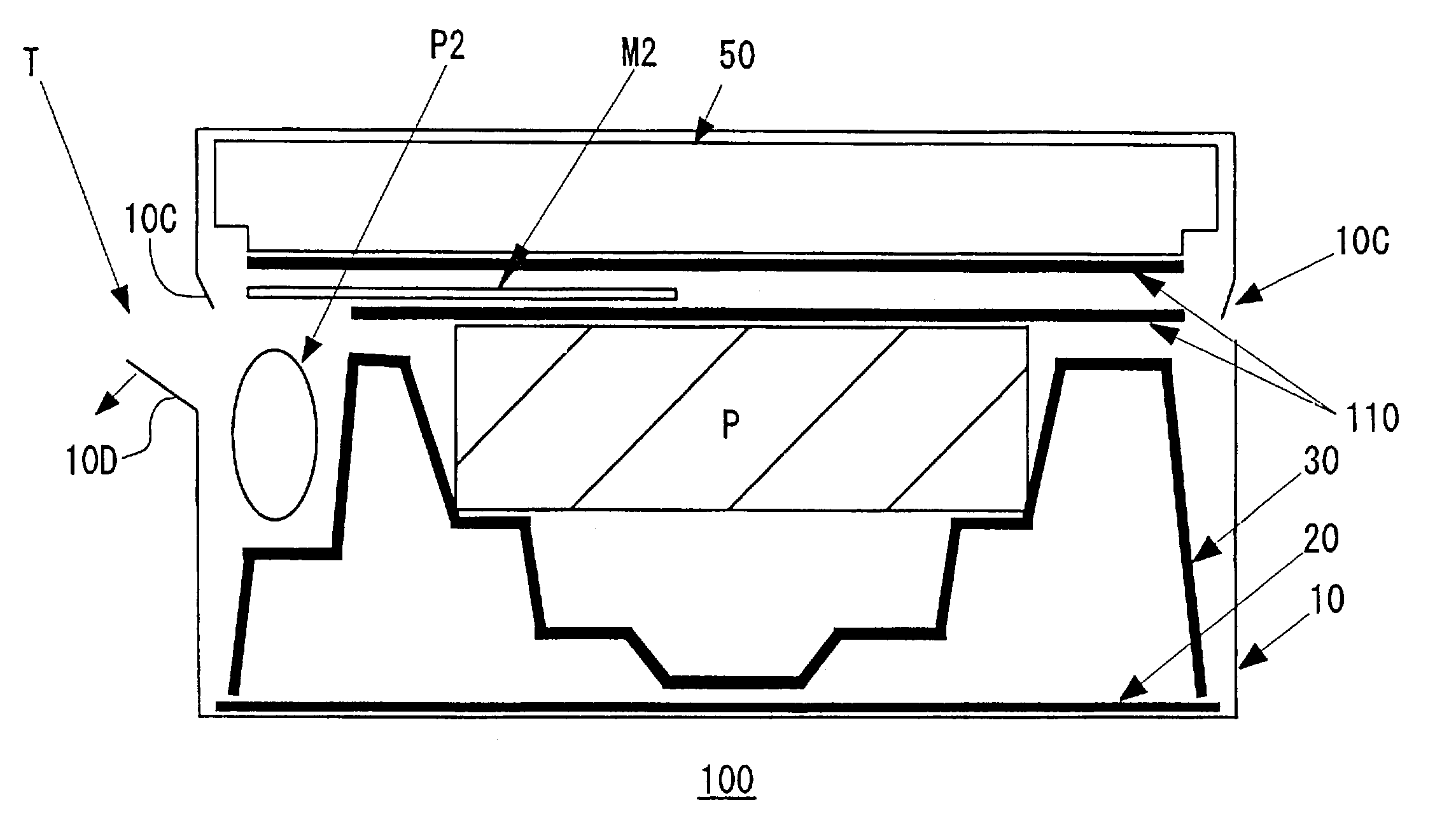
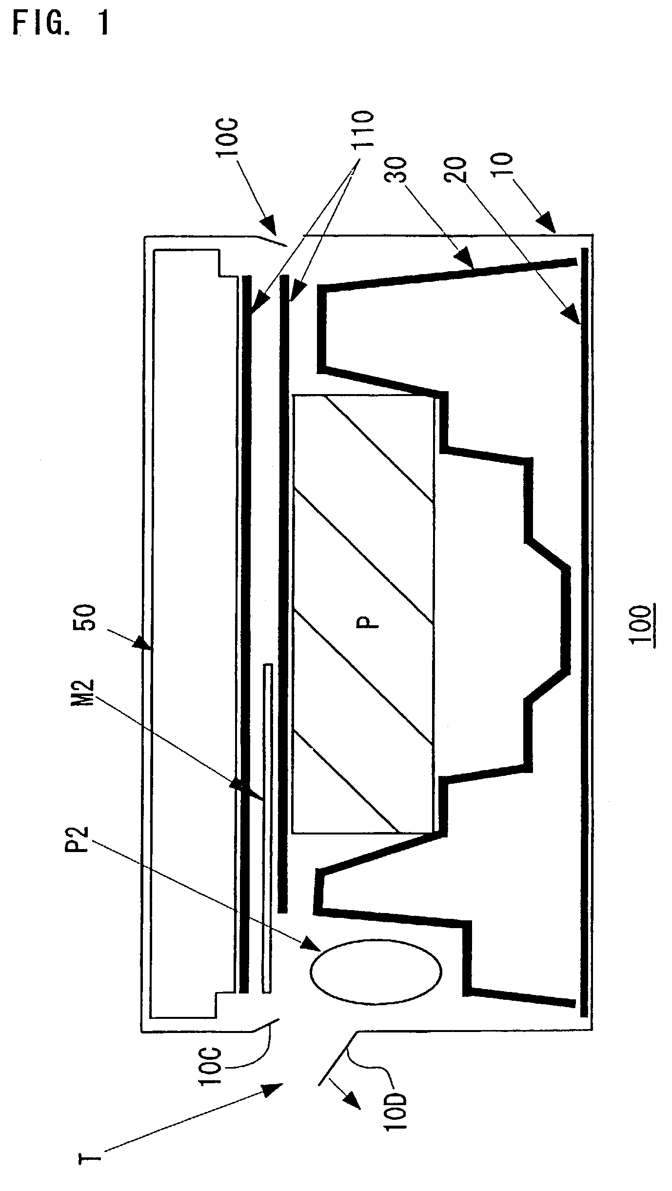
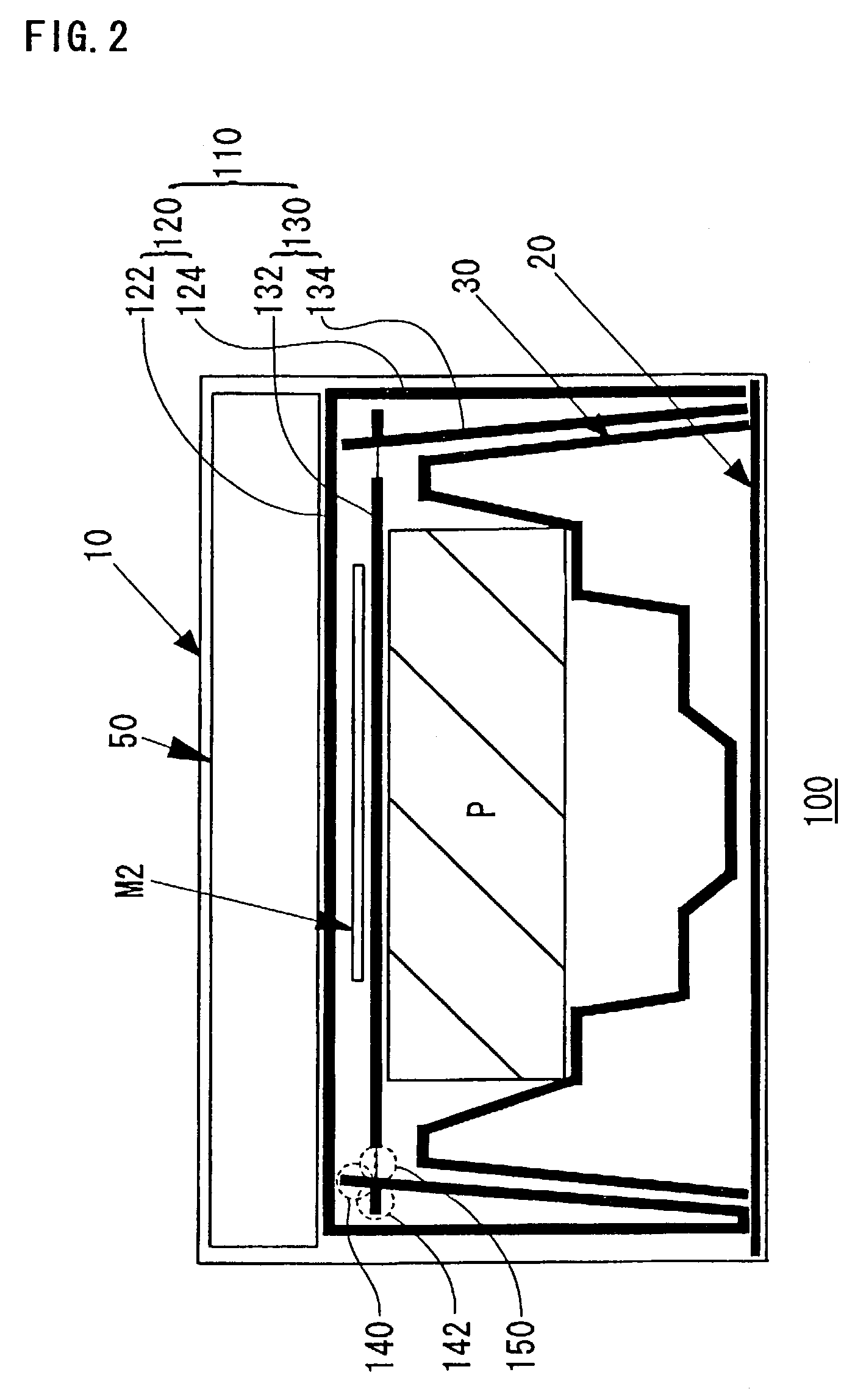
[0063]FIG. 1 and FIG. 2 show a packing article in accordance with exemplary embodiment 1 of the present invention. FIG. 1 is a cross-sectional view from the longitudinal direction. FIG. 2 is a cross-sectional view from the side direction. As shown in FIG. 1 and FIG. 2, a packing article 100 includes a packing box 10, a lower-side buffering member to provide packing 30 including a concave portion, which is located at the lower side of the packing box, locates an item to be packed in the center, an item to be packed P located in the concave portion of the lower-side buffering member 30, a partition member 110 located at the upper side of the item to be packed and a storing member 50, which is located between the partition member 110 and the top surface of the packing box 10, stores an attached part and / or an instruction manual. A lower pad 20 is installed under the lower-side buffering member 30.

[0064]FIG. 3 is a schematic of the partition member 110 in accordance with e...

embodiment 2

[Embodiment 2]

[0078]FIG. 7 is a schematic that shows a packing article 200 in accordance with exemplary embodiment 2 of the present invention. FIG. 8 is a schematic of a partition member 210 according to exemplary embodiment 2. As shown in FIG. 8 and FIG. 9, the partition member 210 according to exemplary embodiment 2 has basically the same structure as the partition member 110 of exemplary embodiment 1. Namely, the partition member 210 of embodiment 2 includes an outside partition member 220 including an upper surface member 222, and an outside skirt portion 224 connected to the upper surface member 222, and an inside partition member 230 including a lower surface member 232 and an inside skirt portion 234 connected to the lower surface member 232.

[0079]The structure of the packing article 200 according to exemplary embodiment 2 utilizes the above mentioned partitioning member 210, instead of a related art partition member 40, so that the number of buffering members to provide pack...

embodiment 3

[Embodiment 3]

[0084]FIG. 9 is a schematic that shows assembling process of packing article of exemplary embodiment 3 of the present invention. The difference between the packing article 300 of exemplary embodiment 3 and the packing article 100 of exemplary embodiment 1 is a portion to store attached parts. Namely, a portion to store attached parts of the packing article 100 of exemplary embodiment 1 is a box for attached parts 50. On the other hand, a portion to store attached parts of the packing article 100 of exemplary embodiment 1 is a tray for attached parts 52. The packing article 300 of exemplary embodiment 3 is basically the same of the packing article 100 of exemplary embodiment 1 except for the above-mentioned structure. The packing article 300 of exemplary embodiment 3 includes the partition member 110 as well as the packing article 100 of exemplary embodiment 1.

[0085]By assembling of the packing article 300 of exemplary embodiment 3, the number of buffering members to pr...


PUM


Abstract

The invention provides a packing article where a packing cost and a transportation fee can be kept low and a buffering function is further enhanced. The invention provides a packing article including: a packing box; a lower-side buffering member to provide packing including a concave portion, which is located at the lower side of the packing box, and which locates an item to be packed in the center; an item to be packed, located in the concave portion of the lower-side buffering member to provide packing; and a partition member located on the upper side of the item to be packed and a storing member, which is located between the partition member and the upper surface of the packing box, and which stores an attached part and/or an instruction manual. The partition member includes an outside partition member, including an upper surface member and an outside skirt portion connected to the upper surface member, and an inside partition member, including a lower surface member and an inside skirt portion connected to the lower surface member.

Description

BACKGROUND OF THE INVENTION[0001]1. Field of Invention[0002]The present invention relates to a packing article where an item to be packed, such as an electronic device, is packed in a packing box, a method of packing an item to be packed, such as an electronic device, in a packing box, and a partition member which is preferably used for the above packing article.[0003]2. Description of Related Art[0004]In the related art, an electronic device or a precise instrument, such as a computer, a printer and / or a projector, can be stored in a packing box with a pair of upper and lower buffering members of packing, which is made of foaming plastic or pulp mold material. The related art also includes a packing article or a method of packing where a buffer member to provide packing, which is made of relatively expensive bubble resin material, is only used for buffering on a lower side and a tray for attached parts, and a box to store attached parts of a product is used to provide buffering on ...

Claims


Application Information

Patent Timeline
IPC IPC(8): B65D85/00B65D5/44B65D5/42B65D5/491B65D5/496B65D5/50B65D77/04B65D81/02B65D81/113
CPCB65D5/4204B65D5/4804B65D5/5028B65D77/042B65D81/025
Inventor KOIKE, MOTOMU
Owner SEIKO EPSON CORP
Why Eureka
Try Eureka