Hose-end sprayer assembly

a technology of hose-end sprayer and assembly, which is applied in the direction of transportation and packaging, combustion types, lighting and heating apparatus, etc., can solve the problem of reducing the effectiveness of chemical substances

Active Publication Date: 2006-10-10
SILGAN DISPENSING SYST CORP
View PDF78 Cites 30 Cited by
  • Summary
  • Abstract
  • Description
  • Claims
  • Application Information

AI Technical Summary

Benefits of technology

[0005]It is therefore an object of the present invention to avoid the aforenoted drawbacks and disadvantages of prior art hose-end sprayers which provide for creating a suction force that draws chemical product into the stream of the carrier liquid in a valve open position, and which have the potential for leakage of carrier liquid into the container through the open vent. This objective is achieved by the provision of venting means in the hose end sprayer assembly which is external to the valve chamber in which the rotatable valve operates for aspirating chemical product into the stream of carrier liquid in a valve open position to effect a mixing of that product on discharge. By isolating the venting means from the valve chamber, any tendency for carrier liquid to enter the container through the open vent is substantially avoided, such that any undesirable dilution of chemical liquid while in its container before being aspirated, is substantially avoided.
[0006]In carrying out this objective, the rotary valve establishes a valve chamber with the transverse bore of the housing in which it is rotatable, and the venting means is external to that valve chamber. Any potential for water entry into the container through the open vent during use of the sprayer is, therefore, prevented. Product is drawn up through the product passage and product duct of the valve into the water carrier stream in the valve open position with the open vent port isolated from the valve chamber to thereby avoid passage of carrier liquid into the chemical product in the container through the open vent which is isolated from the power stream during sprayer operation.

Problems solved by technology

The drawback with such a venting system for this type of sprayer is the tendency during the vent / valve open position for liquid from the carrier passage to enter the container through the gap between 20 and 22, through vent channel 68 and through vent passage 52.
This unwanted liquid, i.e., water, dilutes the chemical product in the container during repeated usage of the sprayer thus reducing the effectiveness of the chemical.

Method used


Image

  • Hose-end sprayer assembly
  • Hose-end sprayer assembly
  • Hose-end sprayer assembly

Examples


Embodiment Construction

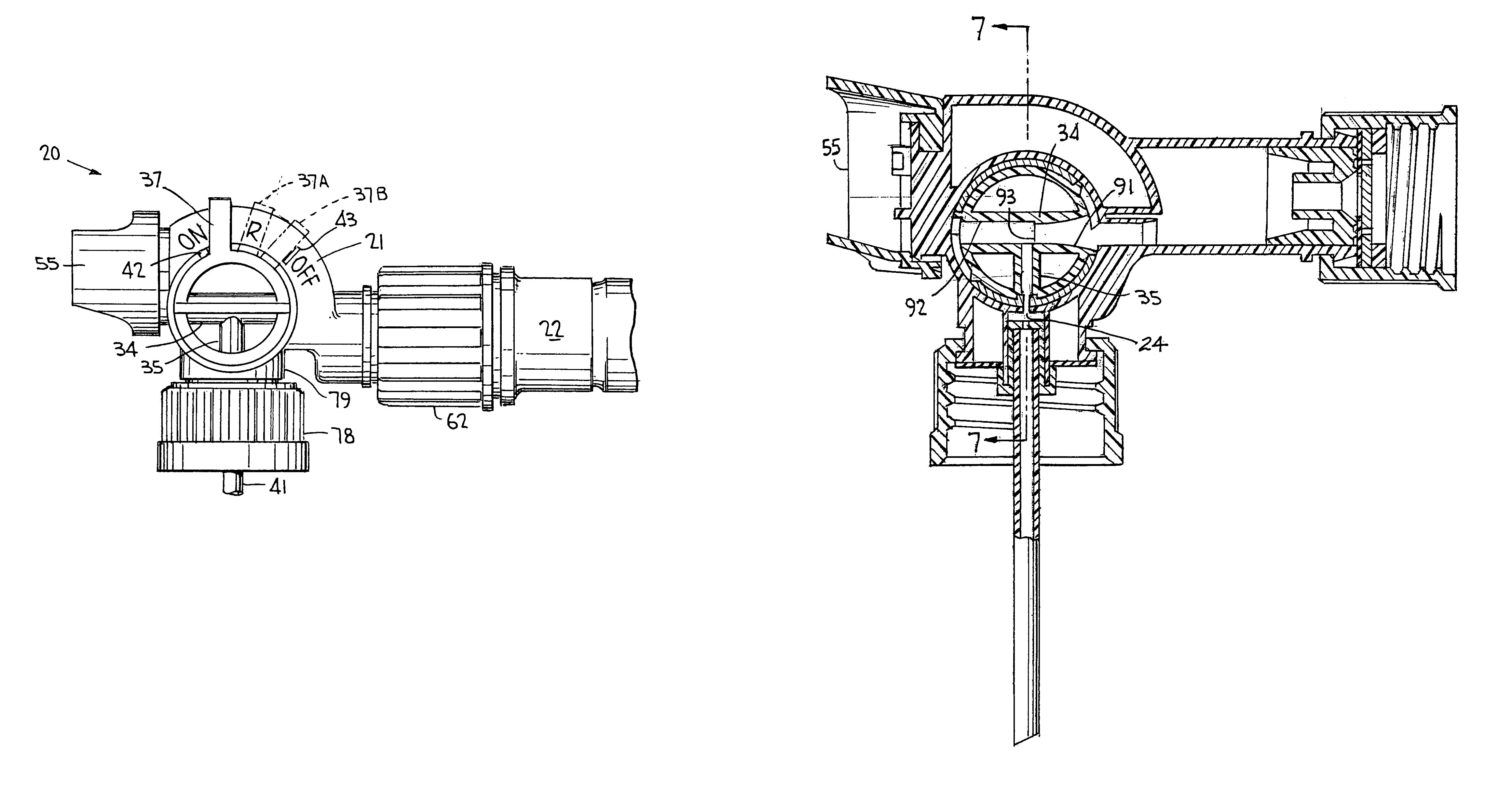
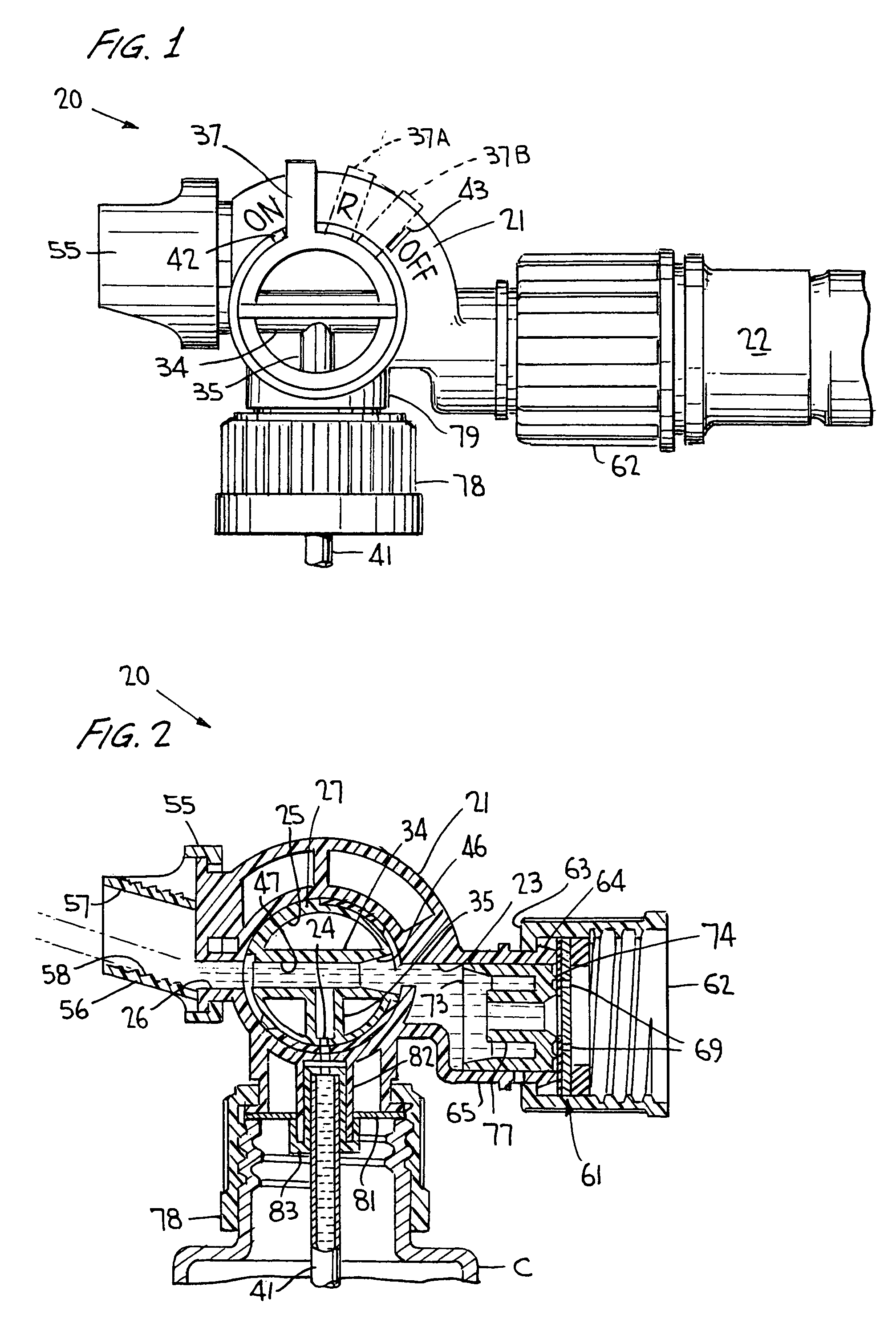
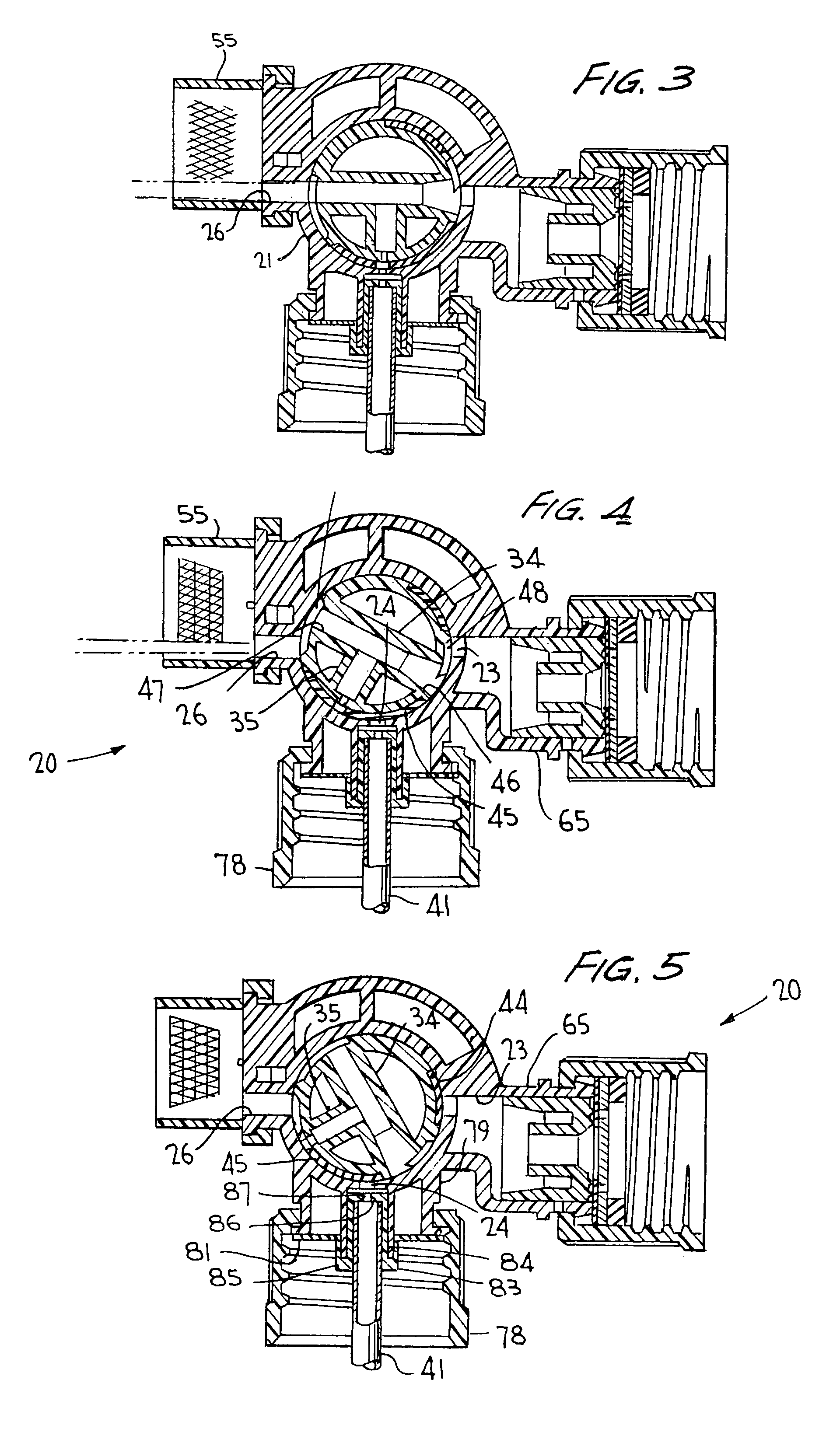
[0017]Turning now to the drawings wherein like reference characters refer to like and corresponding parts throughout the several views, FIGS. 1 to 5 are taken from commonly owned U.S. Pat. No. 6,378,785, except that vent port 38 located in the rotary valve has been eliminated, and vent port 39 in the housing at the location shown has likewise been eliminated. Otherwise, the hose-end sprayer assembly which is generally designated 20 is essentially the same except that gripper bar 52 has now been eliminated, and rotatable nozzle 55 differs slightly in that the downward diversion of the spray made possible by the deflector plate 57, is no longer provided. The general structure of the hose-end assembly according to the invention is otherwise essentially the same as that disclosed in the U.S. Pat. No. 6,378,785 patent, such that further detailed description of the elements and their function will not be duplicated since the same is set forth in detail in that patent, with the entirety of...


PUM


Abstract

A hose-end sprayer has a selectively rotatable rotary valve received within the transverse bore of a housing which includes a carrier liquid inlet passage, a chemical liquid inlet passage and a discharge passage. The valve has a carrier liquid duct and a chemical liquid duct opening into the carrier duct for interconnecting the inlet passage in a first rotative position of the valve, and the valve is capable of closing the inlet passages in a second rotative position of the valve. The rotary valve is selectively rotatable in a third position for interconnecting the liquid passage only with the discharge passage in a rinse position of the valve. Container venting is isolated from a valve chamber in which the rotary valve operates to avoid entry of carrier liquid into the container through the open vent in the ON position of the valve upon its selective rotation.

Description

BACKGROUND OF THE INVENTION[0001]This application relates to a hose-end sprayer of the type set forth in U.S. Pat. No. 6,378,785, commonly owned herewith. This invention is an improvement over the venting feature disclosed in that patent, and the entirety of the disclosure of U.S. Pat. No. 6,378,785 is specifically incorporated herein by reference.[0002]A hose-end sprayer is disclosed in U.S. Pat. No. 6,578,776 which includes a venting feature as required to replenish aspirated product from the container with air to avoid container collapse and any malfunctioning of the system. The sprayer has a cylindrical control valve 20 positioned in a cylindrical transverse bore 22 for rotation between ON and OFF positions. Valve 20 includes a sealing portion 63 that forms an annular seal with bore 22 around the interface between chemical passage 32 and a first passage 56 formed in the valve. The sprayer head assembly includes a vent passage 52 defined by a small hole formed in head 14 of the a...

Claims


Application Information

Patent Timeline
Patent Type & Authority Patents(United States)
IPC IPC(8): B05B7/30F16K11/07B05B7/12B05B7/24B05B15/00B65D47/20
CPCB05B7/2443B05B7/1209B05B7/30B65D47/20
Inventor DODD, JOSEPH K.
Owner SILGAN DISPENSING SYST CORP
Why Eureka
Try Eureka