Spike nail structure

a nail structure and spiking technology, applied in the direction of nails, fastening means, dowels, etc., can solve the problems of deformation or split of the spiking nail b>1/b>, and suffer the effect of reducing the cross section of the piercing

Inactive Publication Date: 2006-10-10
JOKER IND CO LTD
View PDF9 Cites 10 Cited by
  • Summary
  • Abstract
  • Description
  • Claims
  • Application Information

AI Technical Summary

Benefits of technology

[0009]In another aspect of the invention, the second blade has a second point section slightly smaller than a first point section of the first blade so that the second point section is held closely in an indented recess formed on the first point section to shrink the piercing cross section.

Problems solved by technology

The spike nail 1 tends to be deformed or split due to not sufficient strength.
As a result, construction quality suffers.

Method used


Image

  • Spike nail structure
  • Spike nail structure
  • Spike nail structure

Examples


Embodiment Construction

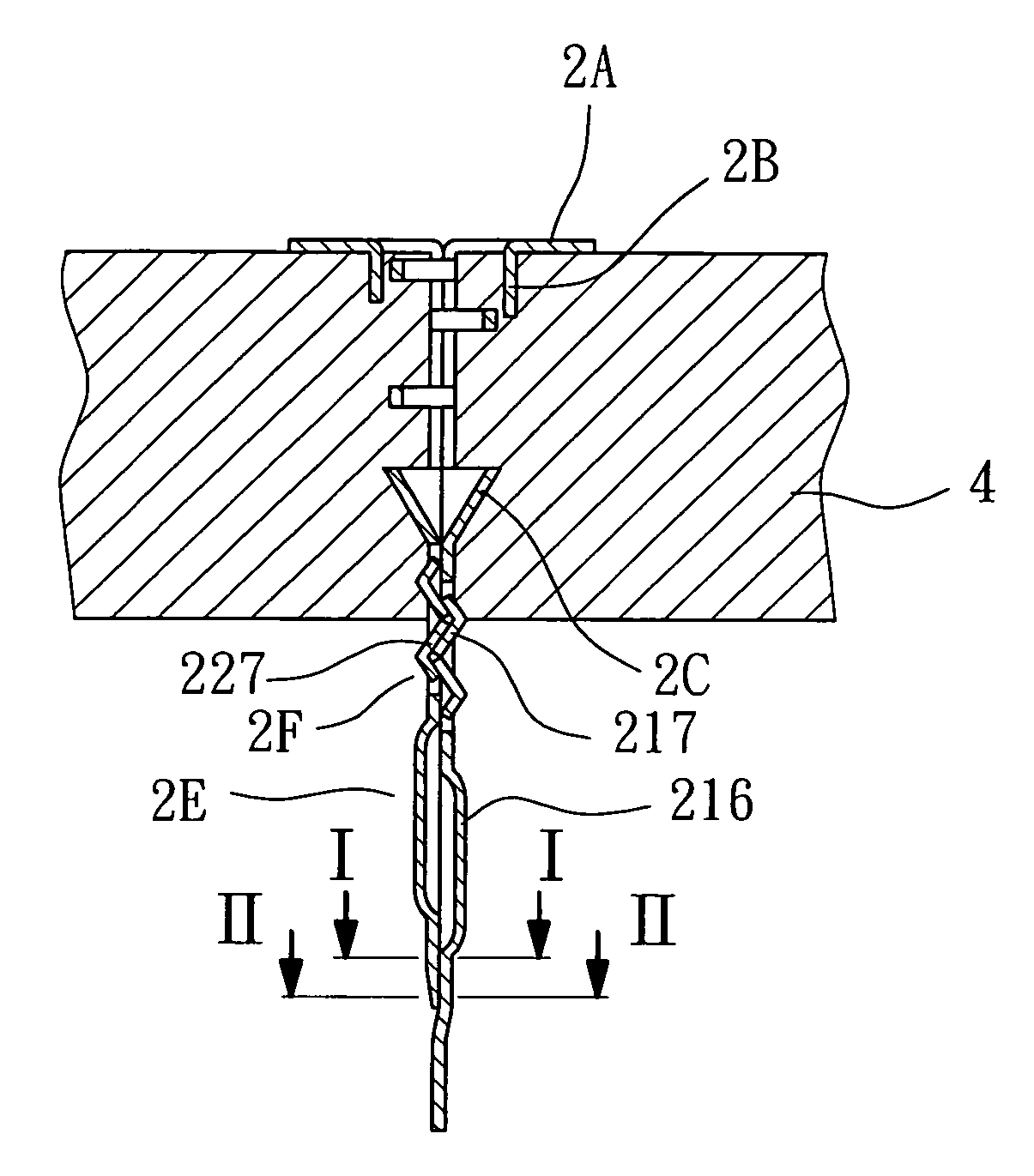
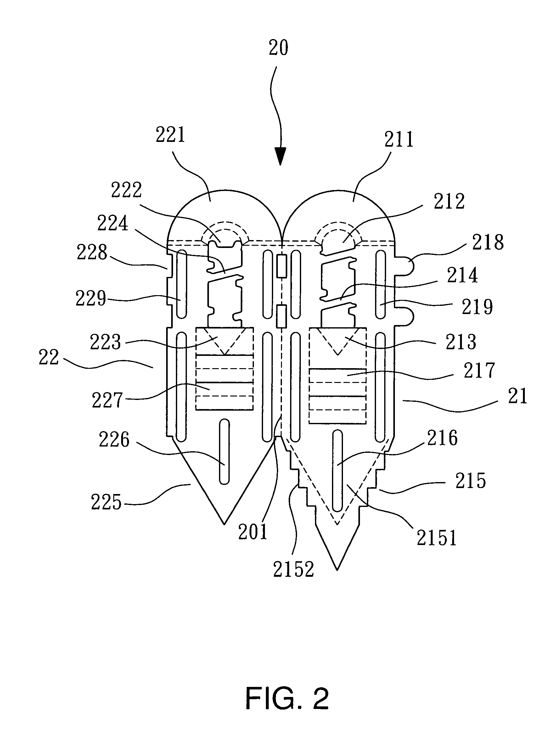
[0025]Referring to FIGS. 2 through 5, the spike nail 2 according to the invention includes a nail body 20 which consists of a first blade 21 and a second blade 22 folded and coupled together about a folding line 201. The nail body 20 includes:

[0026]a striking section 2A located on a upper side of the nail body 20 and formed by bending head sections 211 and 221 outwards that are located respectively on a upper portion of the first blade 21 and the second blade 22. It has a lag spike guiding hole A in the center;

[0027]a upper guiding sleeve 2B formed by extending hole walls 212 and 222 of the lag spike guiding hole A downwards to direct insertion of a lag spike 3;

[0028]a lower guiding sleeve 2C formed by inverted conical walls 213 and 223 and located below the upper guiding sleeve 2B;

[0029]a screw thread guiding section 2D located between the upper guiding sleeve 2B and the lower guiding sleeve 2C on a position of the first blade 21 and the second blade 22 corresponding to each other,...


PUM


Abstract

A spike nail for nailing in walls made of gypsum boards or fiber boards has a nail body which consists of a first blade and a second blade. The nail body includes a striking section, a upper guiding sleeve, a lower guiding sleeve, a screw thread guiding section and a nail point section. The spike nail thus constructed can be nailed into gypsum board or fiber board walls to facilitate hanging articles.

Description

BACKGROUND OF THE INVENTION[0001]1. Field of the Invention[0002]The invention relates to a spike nail structure and particularly to a spike nail for nailing in walls made of gypsum boards or fiber boards to hang articles.[0003]2. Description of the Prior Art[0004]A conventional spike nail 1 (referring to FIG. 1) for nailing in walls made of gypsum boards or fiber boards such as the one disclosed in French patent No. 012420 includes a first blade 11 and a second blade 12 folding together. It has a striking section 13 to receive hitting of a tool to drive a nail point section 14 into a gypsum board or fiber board wall. Then a lag spike may be inserted to drive the first and the second blades apart to anchor the spike nail on the wall W. The lag spike can be used to hang articles. Such a structure still has drawbacks in use, notably:[0005]1. The nail point section 14 of the spike nail 1 is formed by coupling a first nail point 111 of the first blade 11 and a second nail point 121 of th...

Claims


Application Information

Patent Timeline
Patent Type & Authority Patents(United States)
IPC IPC(8): F16B13/13
CPCF16B13/0833F16B13/124F16B15/00
Inventor HUANG, PAN-CHING
Owner JOKER IND CO LTD
Why Eureka
Try Eureka