Compressor blade

a compressor blade and compressor blade technology, applied in the direction of marine propulsion, vessel construction, other chemical processes, etc., can solve the problem of adding weight to the turbofan gas turbine engin

Active Publication Date: 2006-10-10
ROLLS ROYCE PLC
View PDF14 Cites 37 Cited by
  • Summary
  • Abstract
  • Description
  • Claims
  • Application Information

AI Technical Summary

Benefits of technology

[0005]Accordingly the present invention seeks to provide a novel compressor blade, which reduces, preferably overcomes, the above-mentioned problems.

Problems solved by technology

However, these methods of protecting the rear fan containment region add weight to the turbofan gas turbine engine.

Method used


Image

  • Compressor blade
  • Compressor blade
  • Compressor blade

Examples


Embodiment Construction

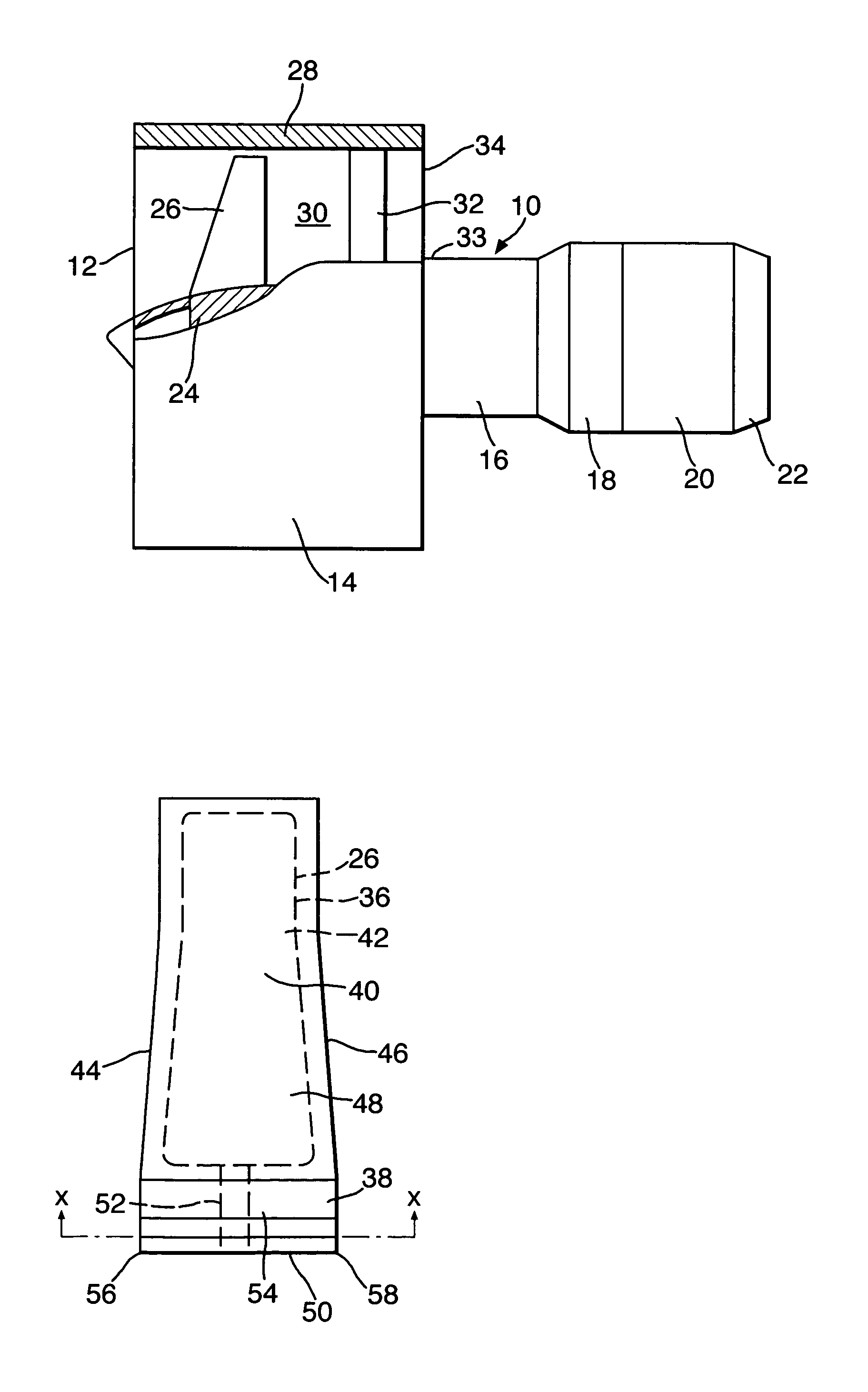
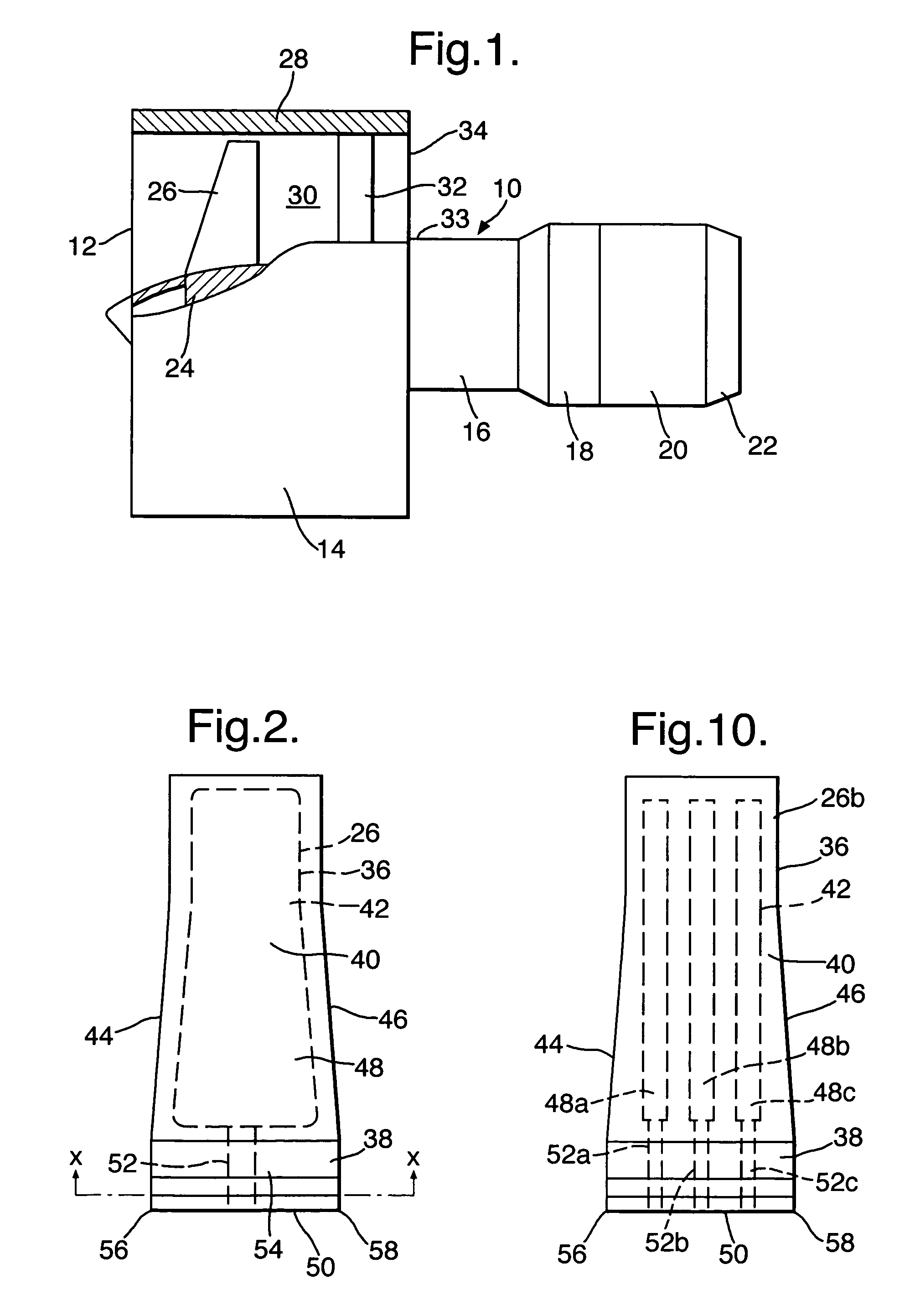
[0032]A turbofan gas turbine engine 10, as shown in FIG. 1, comprises in axial flow series an intake 12, a fan section 14, a compressor section 16, a combustion section 18, a turbine section 20 and an exhaust 22. The turbine section 20 comprises one or more turbine rotors (not shown) arranged to drive one or more compressor rotors (not shown) in the compressor section 16. The turbine section 20 also comprises one or more turbine rotors (not shown) arranged to drive a fan rotor 24 of the fan section 14.

[0033]The fan section 14 comprises a plurality of circumferentially spaced radially outwardly extending fan blades 26 secured to the fan rotor 24. The fan section 14 also comprises a fan casing 28 surrounding and arranged coaxially with the fan rotor 24. The fan casing 28 partially defines a fan duct 30, which has a fan exhaust 34. The fan casing 28 is secured to a core engine casing 33 by a plurality of circumferentially spaced radially extending fan outlet guide vanes 32, which exten...


PUM


Abstract

A compressor blade (26) comprises an aerofoil (36) and a root (38). The aerofoil (36) comprises a concave wall (40) extending from a leading edge (44) to a trailing edge (46) and a convex wall (42) extending from the leading edge (44) to the trailing edge (46). The aerofoil (36) defines at least one internal chamber (48). The root (38) is connected to the aerofoil (36) and the root (38) has a base (50) remote from the aerofoil (38) and at least one aperture (52) extends from the base (50) to the at least one internal chamber (48) in the aerofoil (36). The dimensions, shape and position of the least one aperture (52) are selected such that the root (38) is deformable. This reduces the weight of the containment region of a fan casing (28).

Description

FIELD OF THE INVENTION[0001]The present invention relates to a compressor blade for a turbomachine, and in particular the present invention relates to a fan blade for a turbofan gas turbine engine.BACKGROUND OF THE INVENTION[0002]A turbofan gas turbine engine comprises a fan, which comprises a fan rotor and a number of circumferentially spaced radially outwardly extending fan blades secured to the fan rotor. The fan is surrounded by a fan casing, which defines a fan duct. The fan casing is also arranged to contain one or more of the fan blades in the unlikely event that a fan blade becomes detached from the fan rotor.[0003]If a fan blade becomes detached from the fan rotor, due to impact from a large foreign body, e.g. a bird, the released fan blade strikes a main fan casing containment region. The fan blade generally progressively breaks up under a buckling action. The fan blade increases in strength from the tip to the root and at some position between the tip and the root the rem...

Claims


Application Information

Patent Timeline
Patent Type & Authority Patents(United States)
IPC IPC(8): F01D5/18F01D5/16F01D21/04F04D29/32
CPCF01D5/16F01D5/18F01D21/045F04D29/324Y10S416/50
Inventor READ, SIMON
Owner ROLLS ROYCE PLC
Why Eureka
Try Eureka