Configurable antenna for a wireless access point

a wireless access point and configuration technology, applied in the structural form of individual energised antenna arrays, resonant antennas, radiating elements, etc., can solve the problem of not being able to assume that a new location will have a network socket, significant limitations, and contributing to overall costs

Inactive Publication Date: 2006-10-10
CISCO TECH INC
View PDF4 Cites 36 Cited by
  • Summary
  • Abstract
  • Description
  • Claims
  • Application Information

AI Technical Summary

Problems solved by technology

However, if a laptop or handheld computer is used, it is necessary for the user to disconnect from the network when moving from place to place.
Also, it cannot be assumed that a new location will have a network socket for reconnecting.
This can be a significant limitation in enviromnents where it is important for a user to maintain a constant network connection.
Providing distinct types of AP's contributes to overall expense, with manufacture, packaging, inventory, marketing, etc.
Also, such systems do not offer flexibility to end-users having changing needs, where either throughput or range must be increased in a particular rollout at a later time after the original installation.
Such systems are also not optimal in “hybrid” rollouts where throughput may be required in one portion of the coverage area and range is required in another.
In these instances, the end-users would be required to add additional equipment to their WLAN, resulting in additional expense.

Method used


Image

  • Configurable antenna for a wireless access point
  • Configurable antenna for a wireless access point
  • Configurable antenna for a wireless access point

Examples


Embodiment Construction

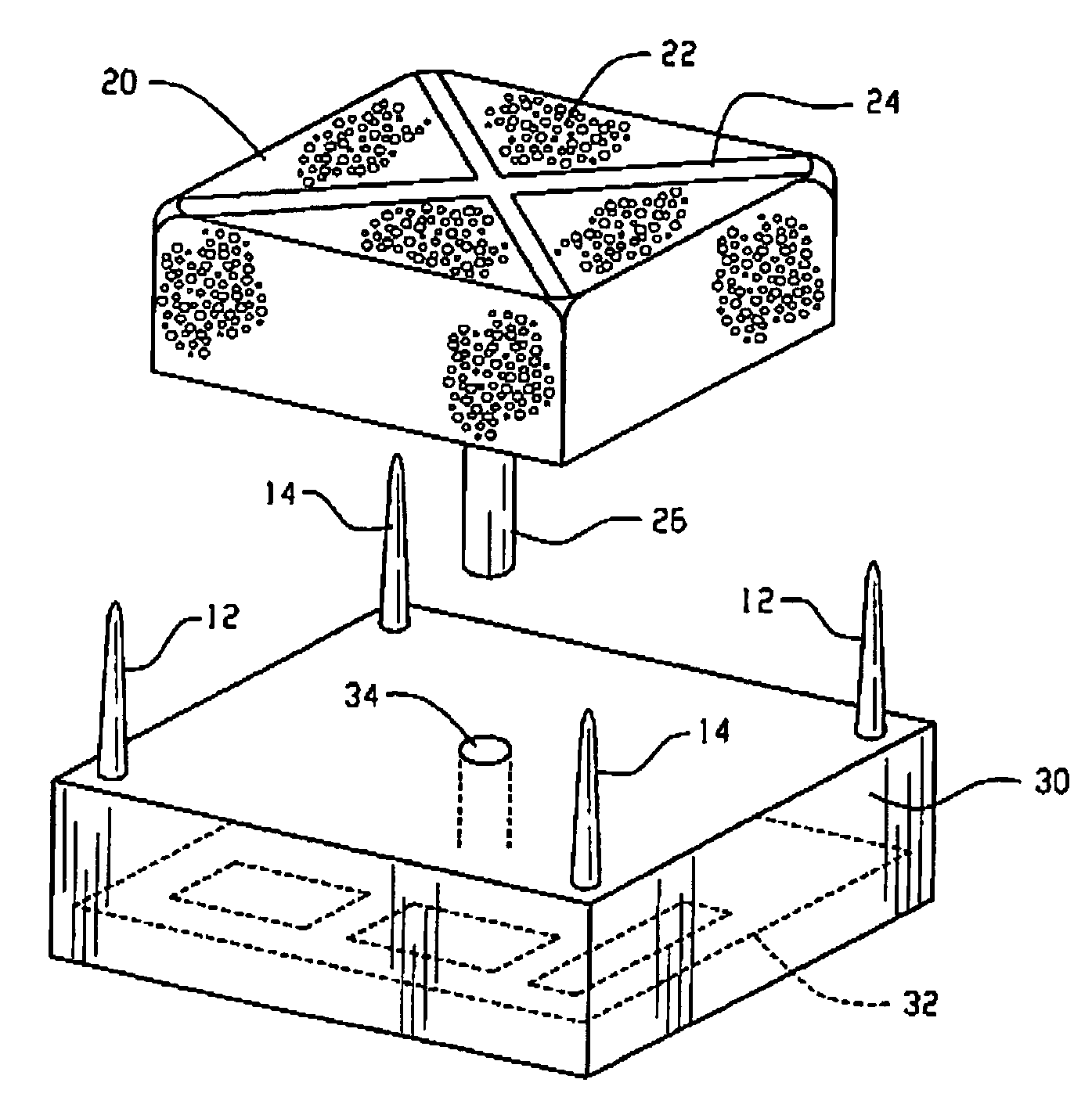
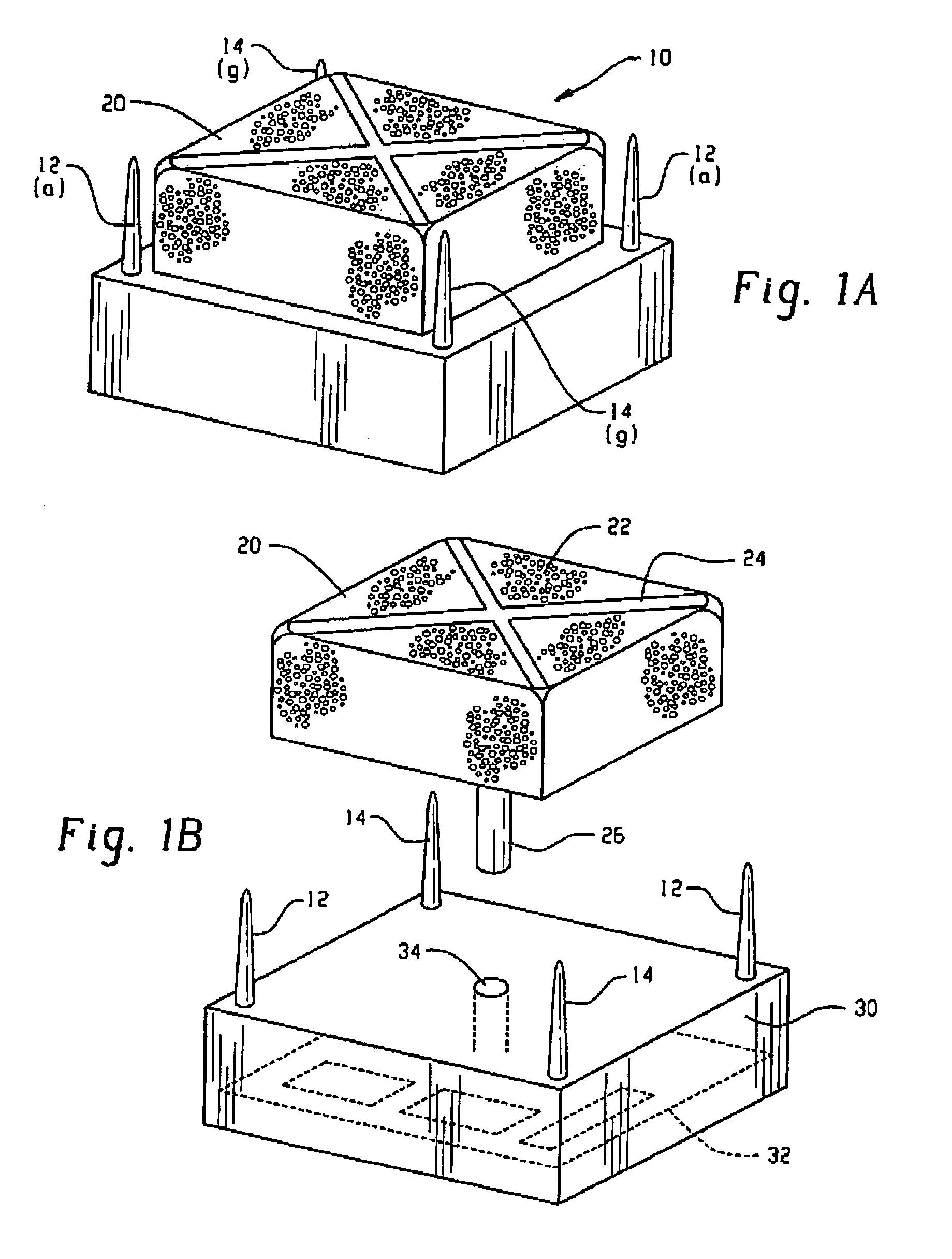
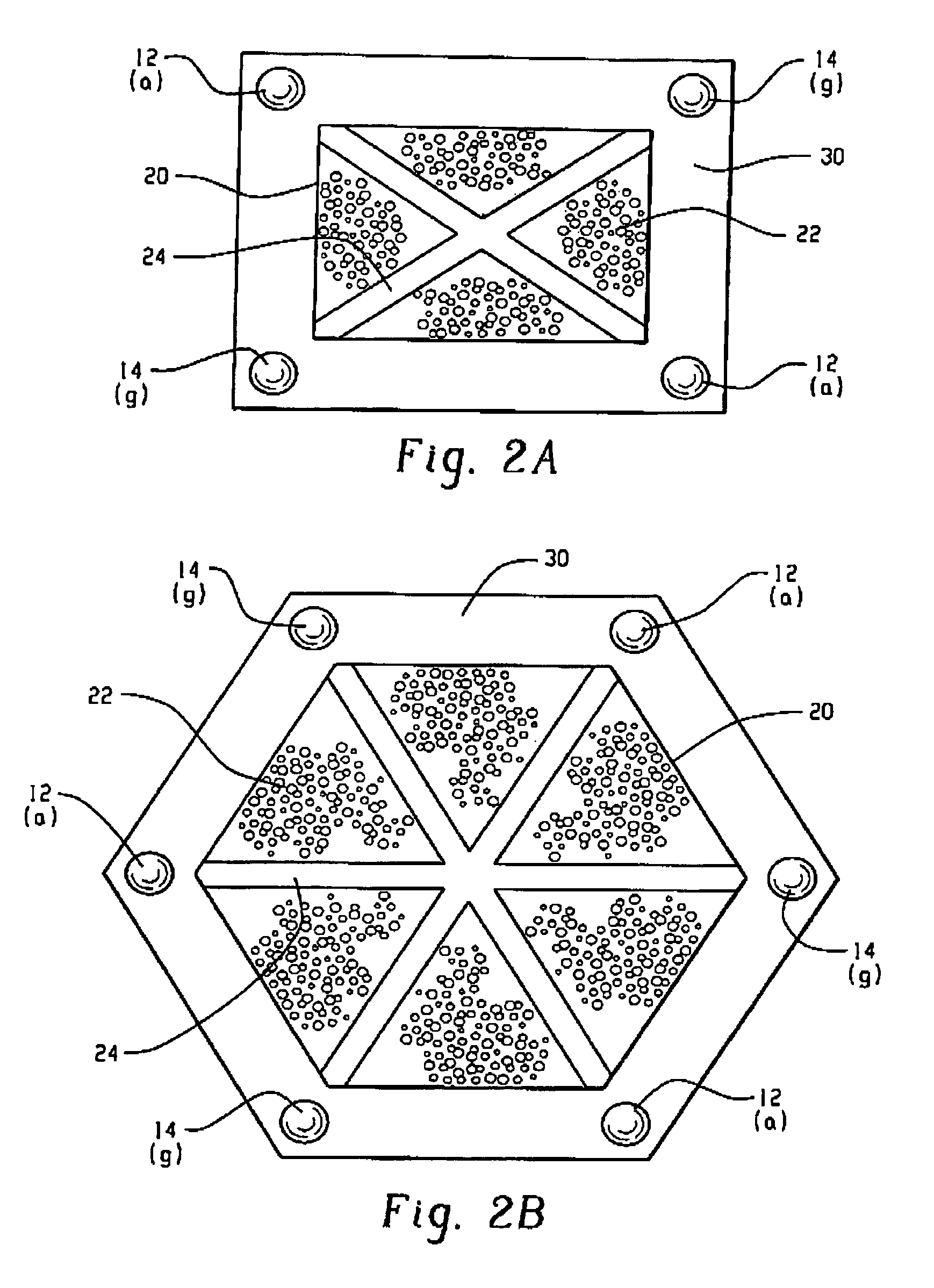
[0006]The difficulties and drawbacks of the previous-type systems are overcome by the present antenna system, alone and in combination with a wireless access point. The present antenna system includes a plurality of antenna elements for providing a respective plurality of communications signals over a wireless channel. An isolating structure is provided, selectively positioned with respect to the antenna elements, for selectively varying signal isolation between the respective antenna elements. In this way, the present system is selectable between a high-throughput / short-range configuration and a low-throughput / long-range configuration.

[0007]As will be realized, the present system is capable of other and different embodiments and its several details are capable of modifications in various respects, all without departing from the invention. Accordingly, the drawings and descriptions are to be regarded as illustrative and not restrictive.

BRIEF DESCRIPTION OF THE DRAWINGS

[0008]FIGS. 1A...


PUM


Abstract

The difficulties and drawbacks of the previous-type systems are overcome by the present antenna system, alone and in combination with a wireless access point. The present antenna system includes a plurality of antenna elements for providing a respective plurality of communications signals over a wireless channel. An isolating structure is provided, selectively positioned with respect to the antenna elements, for selective varying signal isolation between the respective antenna elements. In this way, the present system is selectable between a high-throughput / short-range configuration and a low-throughput / long-range configuration.

Description

BACKGROUND OF THE RELATED ART[0001]The present invention is directed to the field of wireless networking, particularly as applied to different types of wireless networks having different implementation objectives. In a typical local area network (LAN), it is necessary for users to make a “hardware” network connection in which a client device (e.g. a personal computer system) is connected to a wire, which in turn is plugged into a socket for accessing a wired network. However, in using a wired LAN connection, a client device must be operated from a fixed position. This may be acceptable when using a stationary desktop terminal. However, if a laptop or handheld computer is used, it is necessary for the user to disconnect from the network when moving from place to place. Also, it cannot be assumed that a new location will have a network socket for reconnecting. This can be a significant limitation in enviromnents where it is important for a user to maintain a constant network connectio...

Claims


Application Information

Patent Timeline
Patent Type & Authority Patents(United States)
IPC IPC(8): H01Q1/38H01Q1/00H01Q1/22H01Q1/52H01Q3/24H01Q17/00H01Q19/10H01Q21/20
CPCH01Q1/007H01Q1/2258H01Q1/523H01Q17/00H01Q19/10H01Q21/20
Inventor THEOBOLD, DAVID M.LEWIS, MICHAEL E.
Owner CISCO TECH INC
Why Eureka
Try Eureka