
Cooling cloths

a technology of cooling cloths and cloths, which is applied in the field of cooling cloths, can solve the problems of increasing the electric power consumption of the whole society, increasing the cost of air conditioners that have not yet been installed, and health damage, and achieves the effect of simple structure and less power consumption

Inactive Publication Date: 2006-10-17
SEFT DEVMENT LAB
View PDF28 Cites 27 Cited by
  • Summary
  • Abstract
  • Description
  • Claims
  • Application Information

AI Technical Summary

Benefits of technology

"The present invention provides a cooling suit for a wearer that allows for comfortable wear with less power consumption and a simple structure. The cooling suit includes a cloth part and at least one spacer that creates an airflow passage between the cloth part and the wearer's body. The spacer has an opening ratio of at least 30% in the plane perpendicular to the air flow. The cooling suit can be worn on the upper or lower body of the wearer and can be unitedly worn on both the upper and lower body. The air-blowing means forcibly causes an airflow within the airflow passage. The power source means supplies electric power to the air-blowing means. The technical effect of the invention is to provide a cooling suit that allows for comfortable wear with less power consumption and a simple structure."

Problems solved by technology

However, air conditioners are so expensive that they have not been yet installed in every room of a household, though the spread rate of air conditioners to households has been increased in itself.
Further, since air conditioners consume a lot of electric power, the spread of air conditioners: increases the electric power consumption of the whole society; and causes a disappointed result of warming the whole earth under the circumstances that the major part of power generation relies on fossil fuels.
Moreover, air conditioners for directly cooling the air in the pertinent rooms may cause a problem of health damage due to overcooling.

Method used


Image

  • Cooling cloths
  • Cooling cloths
  • Cooling cloths

Examples


Embodiment Construction

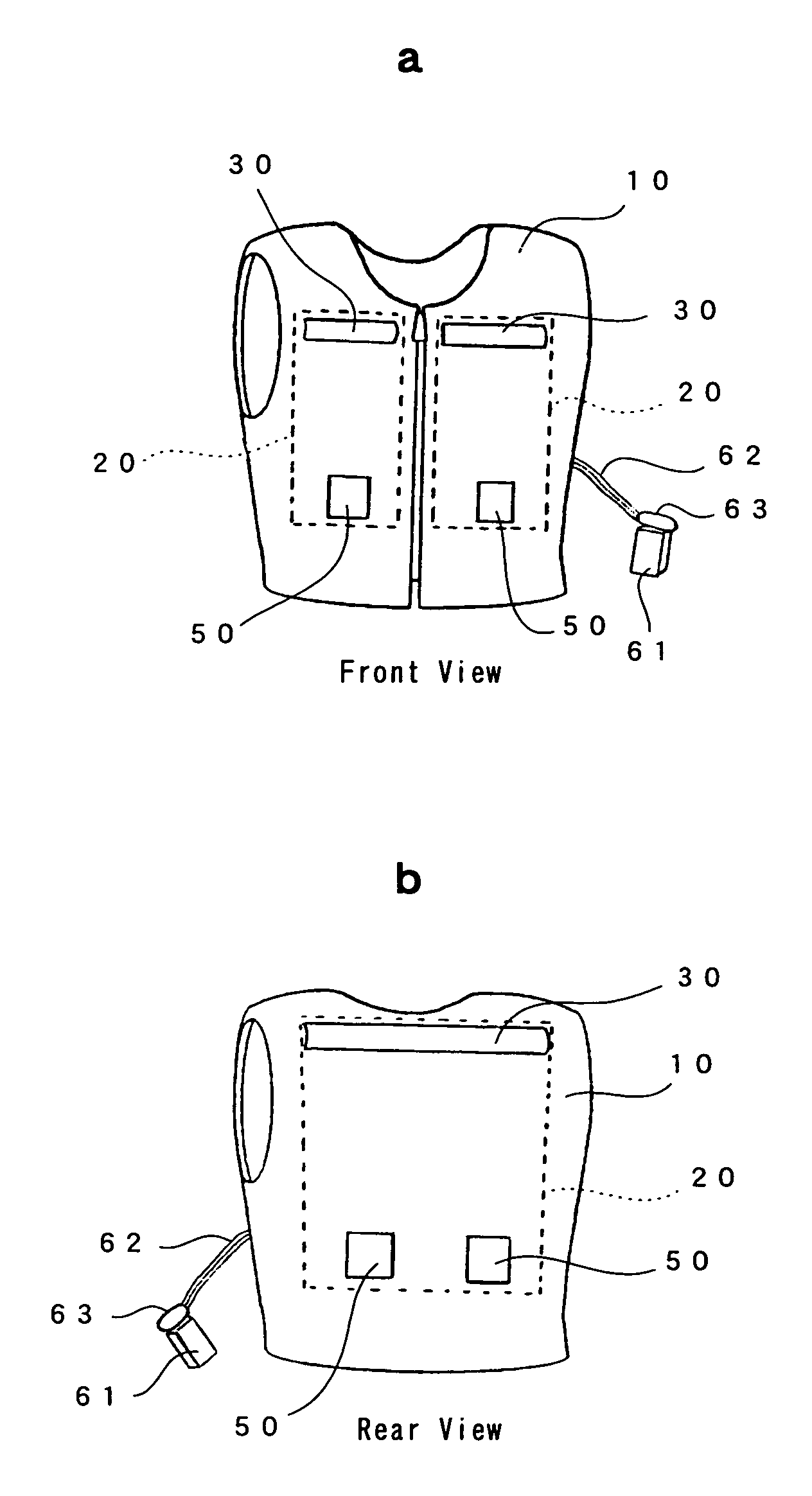
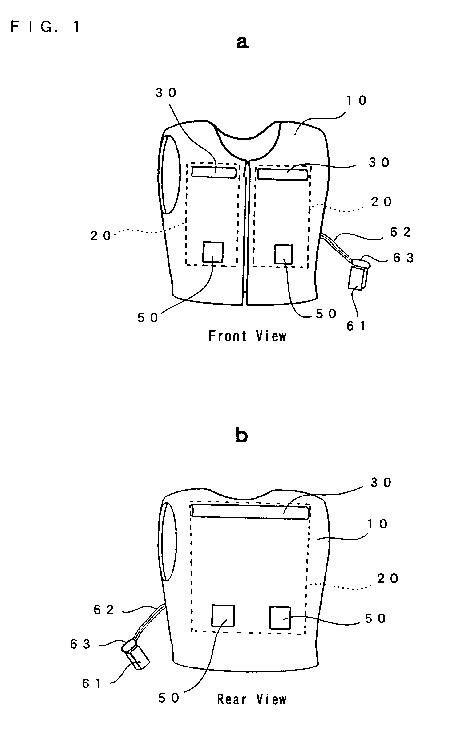
[0028]There will be described hereinafter the best mode for carrying out the present invention, with reference to the accompanying drawings. FIG. 1a is a schematic front view of a cooling suit according to an embodiment of the present invention, and FIG. 1b is a schematic rear view of the cooling suit.

[0029]As shown in FIG. 1, the cooling suit of this embodiment comprises a cloth part 10, three spacers 20, three air inlets 30, four air outlets, four fans (air-blowing means) 50, a battery (power source means) 61, connection cords 62 and a battery attachment 63. Here, there will be described a situation where the cooling suit is applied to a vest. This vest is a type of closing the front by a fastener.

[0030]The cloth part 10 has a reverse side which is sewn or patched with three spacers 20 with thread. In this embodiment, the spacers 20 are sewn to those positions of the cloth part 10 which are susceptible to perspiration, respectively, such as a left thorax, right thorax and back. Th...


PUM


Abstract

A cooling suit comprises: a cloth part; at least one spacer provided at a predetermined position of a reverse side of the cloth part, so as to ensure an airflow passage between the cloth part and a wearer's body; an air inlet provided at the cloth part so as to introduce air from the exterior into the airflow passage; an air outlet provided at the cloth part so as to take out the air within the airflow passage; a fan for forcibly causing an airflow within the airflow passage; and a battery for supplying an electric power to the fan.

Description

TECHNICAL FIELD[0001]The present invention relates to a cooling suit for allowing to feel comfortableness even in environments at higher temperatures.BACKGROUND ART[0002]Currently, air conditioners are widespread most, as means for overcoming hotness in hot seasons such as summer. Such air conditioners are extremely effective in overcoming hotness, since they are to directly cool the air in the pertinent rooms.[0003]However, air conditioners are so expensive that they have not been yet installed in every room of a household, though the spread rate of air conditioners to households has been increased in itself. Further, since air conditioners consume a lot of electric power, the spread of air conditioners: increases the electric power consumption of the whole society; and causes a disappointed result of warming the whole earth under the circumstances that the major part of power generation relies on fossil fuels. Moreover, air conditioners for directly cooling the air in the pertinen...

Claims


Application Information

Patent Timeline
Patent Type & Authority Patents(United States)
IPC IPC(8): A41D27/02F25D25/00F28F1/00A41D13/002A41D13/005
CPCA41D13/0025Y10S2/03
Inventor ICHIGAYA, HIROSHI
Owner SEFT DEVMENT LAB
Learn More