This helps you quickly interpret patents by identifying the three key elements:
Problems solved by technology
Method used
Benefits of technology
Benefits of technology
[0031]the O-ring member arranged so as to be fitted in the interlock groove of the sliding shaft, thereby enabling detachably securing the wristwatch tool component to the front end portion of the sliding shaft.
[0061]According to still a further aspect of the present invention, there is provided a hold guide member of substantially clip configuration, comprising a pair of clip hold members and a connecting part adapted to couple the clip hold members at base end portions thereof in curved form to thereby impart elasticity,
[0063]The hold guide member according to still a further aspect of the present invention may be characterized in that the connecting part is provided with a pin catcher part consisting of a recessed part of through hole configuration adapted to hold a connecting pin so as to prevent dropping of the connecting pin.
Problems solved by technology
However, in the use of conventional band connecting pin removing tool, occasionally, pins cannot be removed without the application of great force because of the crush of hole for insertion of a band connecting pin or the dislocation of position of hole between band pieces.
Therefore the tip pin would be bent or be broken.
Further, human press force is limited, so that failure to remove band connecting pins has been experienced when the band connecting pins are rusted or when dust or the like sticks to the holes for insertion of band connecting pins.
With respect to the chamfered case back of wristwatch case as well, failure to remove it by wrenching has been experienced when the chamfer portion has been deformed or rusted.
Method used
Image
Click on the blue label to locate the original text in one second.
Reading with bidirectional positioning of images and text.
Examples
first embodiment
[0101]the present invention will now be described with reference to drawings
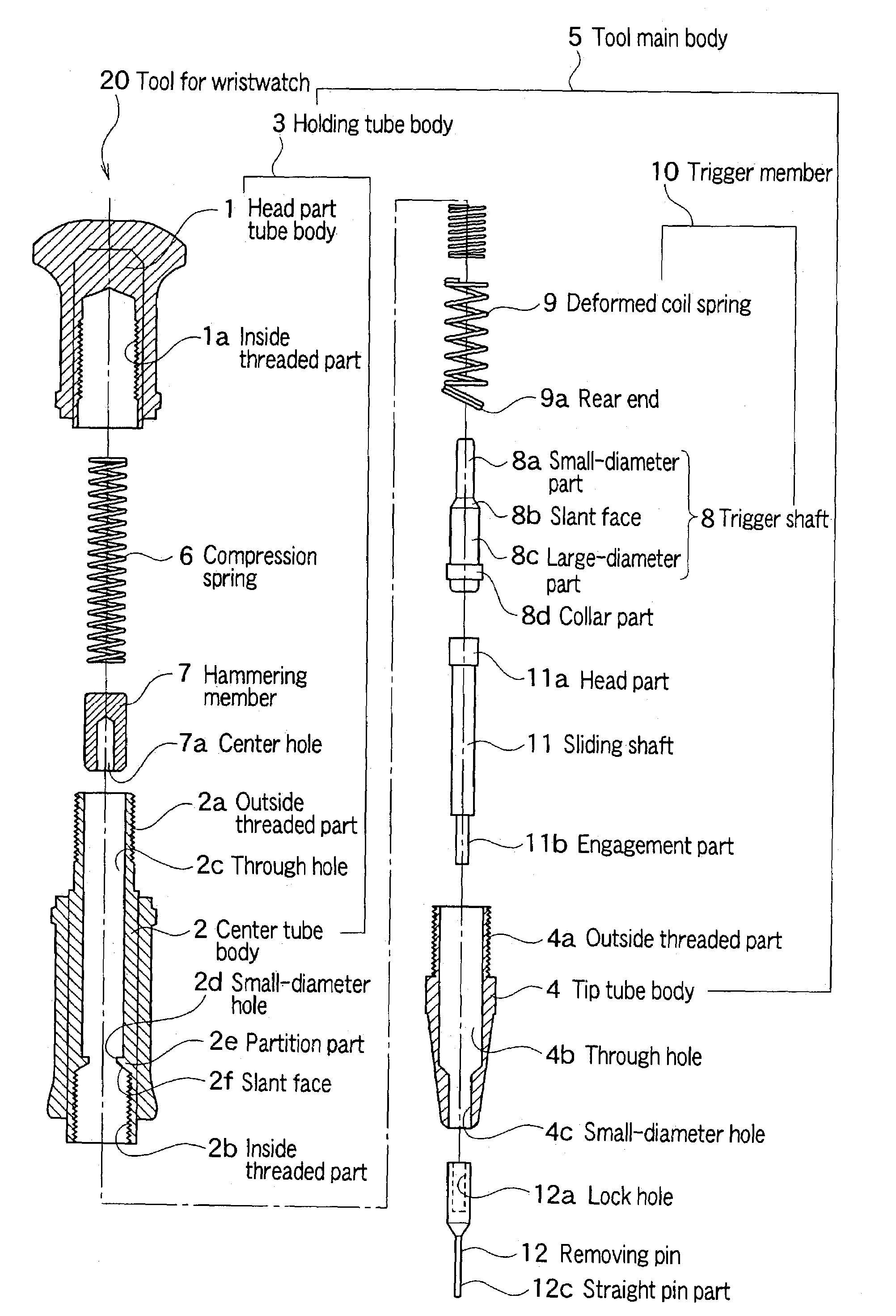
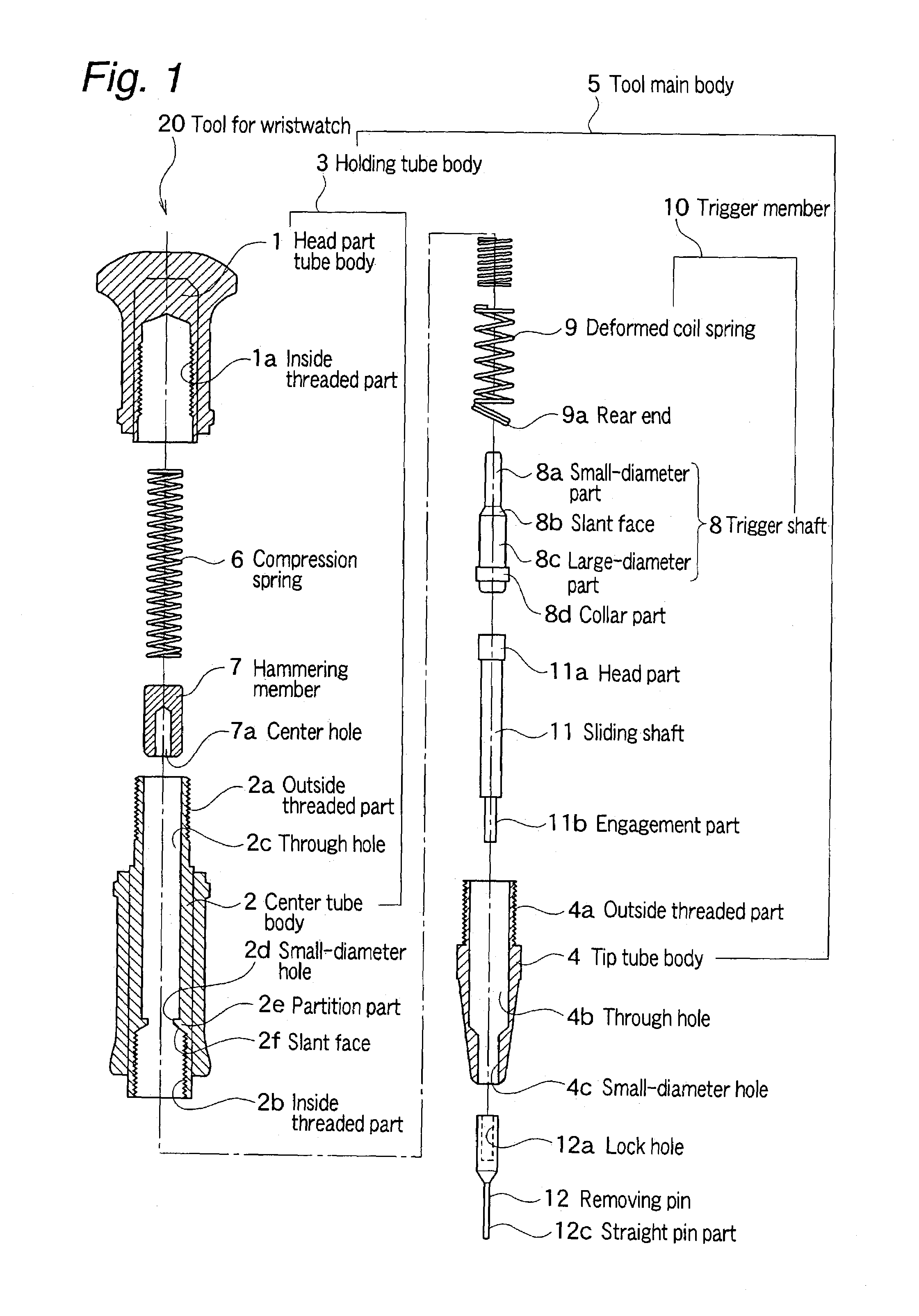
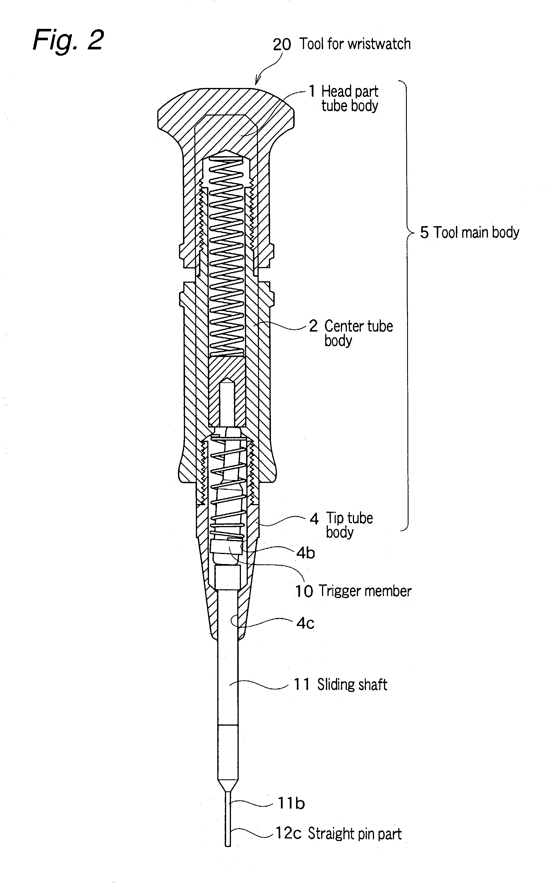
[0102]FIG. 1 is an exploded sectional view of a tool for removing a band connecting pin, which is a first form of tool for wristwatch according to the present invention. FIG. 2 is a sectional view of the above tool for wristwatch after assembly. FIGS. 3 to 5 are sectional views explaining operating conditions of the above tool for wristwatch.
[0103]The construction of the first form of tool for wristwatch according to the present invention will now be described. Referring to FIG. 1, numeral 20 generally denotes one form of tool for wristwatch according to the present invention.
[0104]As shown in FIG. 1, the tool for wristwatch 20 at its upper end portion includes substantially cylindrical head part tube body 1 having its one end closed. The inner wall of the head part tube body 1 is provided with inside threaded part 1a. Moreover, at the lower part of this head part tube body 1, substantially cylindrical cente...
second embodiment
[0142]Nextly, the present invention will be described with reference to drawings.
[0143]FIG. 6 is a partial sectional side view of a tool for removing a band connecting pin, which is a tool for wristwatch according to the second embodiment of the present invention.
[0144]In FIG. 6, numeral 30 denotes pliers. Numeral 21 denotes a one-side functioning part of the pliers, and numeral 22 denotes an other-side functioning part of the pliers. Numeral 23 denotes a fulcrum of both of the functioning parts 21, 22. The front end portion of the one-side functioning part 21 is bent at substantially a right angle so that a hook part 21a is formed. Perpendicular line from the fulcrum 23 crosses on the extension line L of the inside outline of the hook part 21a.
[0145]Numeral 24 denotes a wristwatch band receiving member as an exterior part fixing jig, which is secured to an outside portion of front end of the other-side functioning part 22. The band receiving member 24 is provided with a through ho...
third embodiment
[0157]Nextly, the present invention will be described with reference to drawings.
[0158]FIG. 7 is a plan view of a tool component for opening a wristwatch case back or bezel according to the third embodiment of the present invention. FIG. 8 is a view of a section on the line A—A of FIG. 7. FIG. 9 is a plan view of a tool for opening a case back or bezel, which is fixed to the sliding shaft.
[0159]In FIGS. 7 and 8, numeral 31 denotes a wrench which is a tool component for opening a wristwatch case back or bezel. This wrench is secured to the sliding shaft 11 at the front end of the tool for wristwatch as described in the first embodiment, and provides means for opening a case back or bezel.
[0160]Edge part 31a of acute angle section is provided at the front end of the wrench 31. Further, a nonthrough shaft hole 31c, which is the engagement section with the sliding shaft 11, is formed in the center of the rear end surface of the wrench 31. Moreover, a threaded hole 31b for setscrew, for ...
PUM
Property
Measurement
Unit
Length
aaaaa
aaaaa
Force
aaaaa
aaaaa
Pressure
aaaaa
aaaaa
Abstract
Substantially cylindrical head tube body, center tube body and tip tube body threadedly engage each other to thereby construct a tool main body of a tool for wristwatch. The through hole of the center tube body is provided with a partition part having a small-diameter hole and slant face. A hammering member and compression spring are slidably accommodated in the through hole. A trigger shaft includes a small-diameter part which can be inserted in a center hole of the hammering member, and a large-diameter part continuing therefrom through the slant face, which can pass through the small-diameter hole. A deformed coil spring has the large-diameter part of the trigger shaft fitted therein in wound form, and energizes the trigger shaft toward sliding shaft while slanting the trigger shaft so as to cause the small-diameter part to shift toward the inside wall of the tool main body. The sliding shaft at its rear end includes large-diameter head part and at its front end includes an engagement part to which a wristwatch tool component can be replaceably fixed. The engagement part interlocks a small-diameter hole of the tip tube body with a play, and the front end of the engagement part protrudes from the tip tube body.
Description
TECHNICAL FIELD[0001]The present invention relates to a wristwatch tool for removing a band connecting pin, a case back, and other exterior parts of a wristwatch.DESCRIPTION OF THE PRIOR ART[0002]Among the common wristwatch bands, there are those having a plurality of band pieces or links connected to each other by means of band connecting pins. In these common wristwatch bands, the number of band pieces or links is regulated by removing or inserting band connecting pins, so that the band length can be adjusted. These band connecting pins removed or inserted are called adjust pins. Further, the band connecting pins are also used to connect a band center buckle. The band connecting pins are buried in, for example, band pieces or links, so that a special purpose band connecting pin removing tool is needed for removing operation therefor.[0003]An example of a conventional general band connecting pin removing tool, is disclosed in, for example, Japanese Utility Model Registration No. 25...
Claims
Application Information
Patent Timeline
Application Date:The date an application was filed.
Publication Date:The date a patent or application was officially published.
First Publication Date:The earliest publication date of a patent with the same application number.
Issue Date:Publication date of the patent grant document.
PCT Entry Date:The Entry date of PCT National Phase.
Estimated Expiry Date:The statutory expiry date of a patent right according to the Patent Law, and it is the longest term of protection that the patent right can achieve without the termination of the patent right due to other reasons(Term extension factor has been taken into account ).
Invalid Date:Actual expiry date is based on effective date or publication date of legal transaction data of invalid patent.

