Axial piston machine having a device for the electrically proportional adjustment of its volumetric displacement

a technology of proportional adjustment and axial piston machine, which is applied in the direction of machines/engines, mechanical devices, and positive displacement liquid engines, etc., can solve the problems of large overall width, structurally induced problems of known feedback mechanisms, and adversely affecting the desired proportional adjustment characteristic of adjustment devices

Active Publication Date: 2006-10-17
DANFOSS POWER SOLUTIONS INC
View PDF6 Cites 14 Cited by
  • Summary
  • Abstract
  • Description
  • Claims
  • Application Information

AI Technical Summary

Benefits of technology

[0013]A great advantage of the present invention is that an entire series of axial piston machines with different volumetric displacements can be covered with the adjustment device, it being possible to use the same adjustment device for all models of the series by using the pointer.
[0014]Further refinements and advantages of the invention emerge from the subsequent description of the figures.

Problems solved by technology

Known feedback mechanisms have structurally induced problems.
On the one hand, any form of mechanical hysteresis between levers, springs and proportional magnets adversely affects the desired proportional adjustment characteristic owing to the sensitive equilibrium of forces, and on the other hand previous solutions require differently dimensioned adjustment devices depending on the overall size of the axial piston machine, which adjustment devices give rise to large overall widths in some cases owing to the lever mechanisms which are used.
Since they are mounted on an exposed position on the axial piston machine, this increases the risk of damage and makes it unsuitable to use such adjustment units on axial piston machines with a small volumetric displacement and correspondingly small installation space.

Method used


Image

  • Axial piston machine having a device for the electrically proportional adjustment of its volumetric displacement
  • Axial piston machine having a device for the electrically proportional adjustment of its volumetric displacement
  • Axial piston machine having a device for the electrically proportional adjustment of its volumetric displacement

Examples


Embodiment Construction

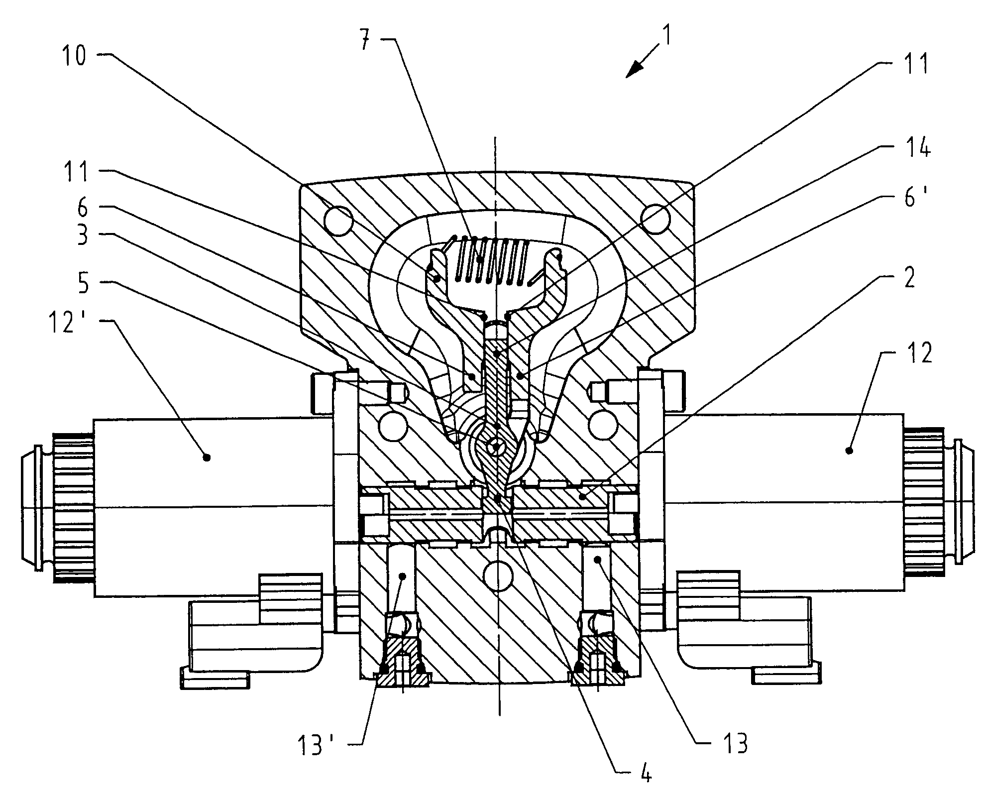
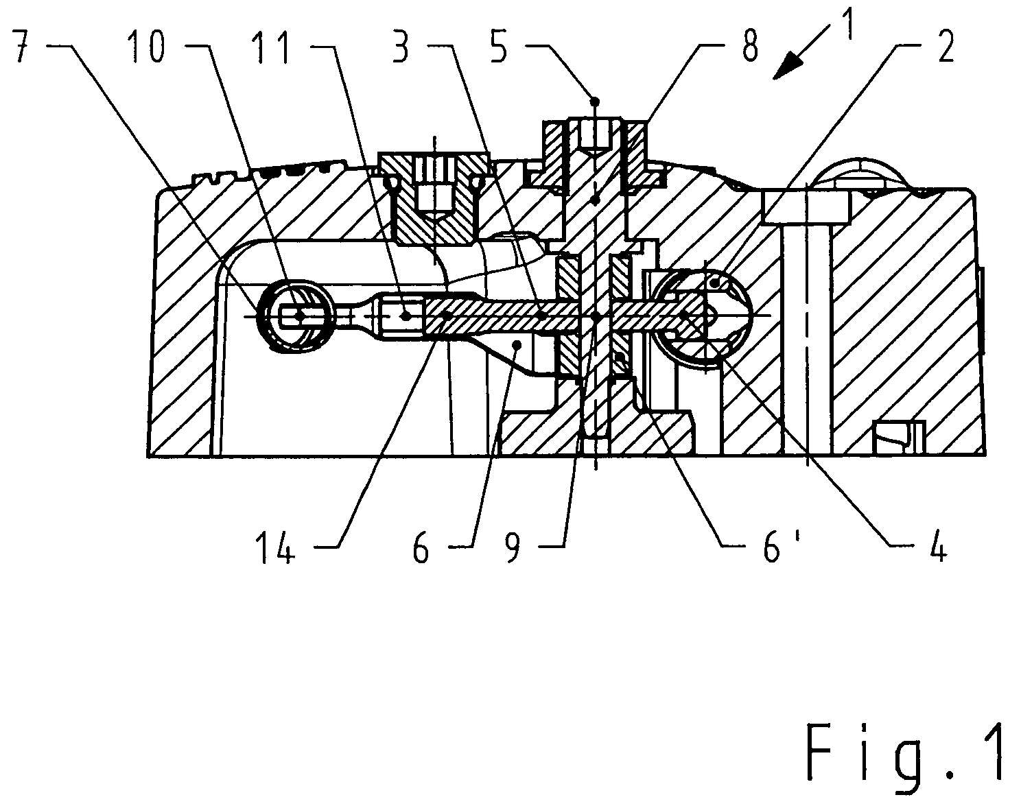
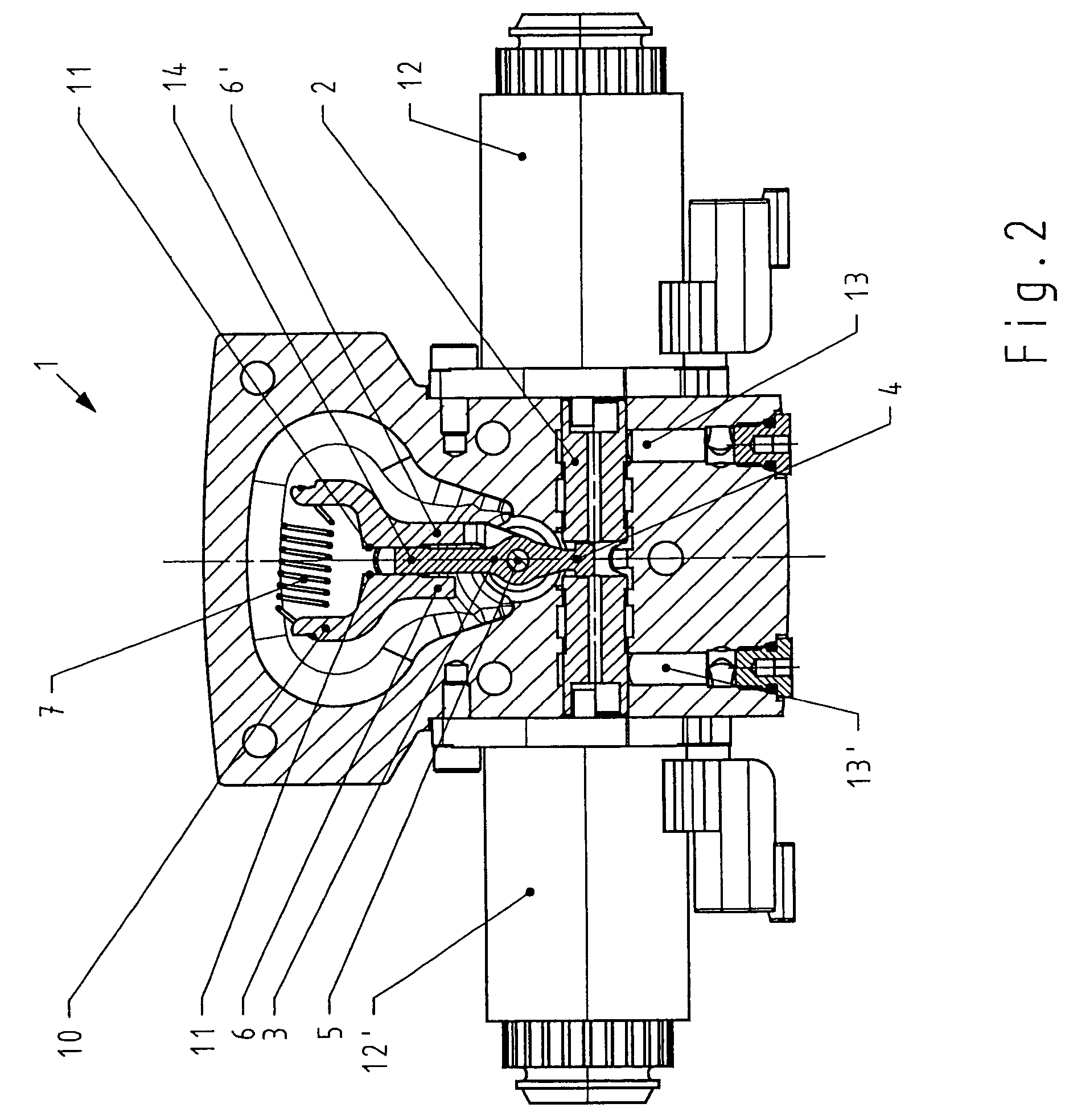
[0021]FIG. 1 shows a cross section through the adjustment device 1. A control piston 2 is adjusted along a movement axis perpendicularly to the cross section shown by means of proportional magnets, with the result that an oil pressure which acts on the servopistons (not shown here) is made available. A pointer 3 which is embodied as a two-armed lever engages in the control piston 2, which, with its movement, rotates the pointer 3 about the pivot axis 5. The pointer 3 is guided here in a bore of the control piston 2 outside its movement axis and centre line, by means of a ball guide 4.

[0022]On each side of the pointer 3, a spring lever 6, 6′ is also mounted on the pivot axis 5, this bearing being embodied in such a way that tilting moments are avoided as far as possible. Such tilting moments can be produced by the forces which are exerted on the spring levers 6, 6′ by the control piston 2 and by the traction spring 7 which stresses the spring levers one against the other. It is possi...


PUM


Abstract

An axial piston machine having a swash plate or oblique axis which can be adjusted by means of servopistons and has a valve segment and an adjustment unit for the electrically proportional adjustment of the volumetric displacement, the adjustment unit comprising proportional magnets which can be activated electrically, and a control piston for controlling the oil pressure which moves the servopistons, the proportional magnets acting on this control piston along a common tappet axis. A feedback device for feeding back the current swash plate or oblique axis valve segment position is provided. The feedback device comprises spring levers and a pointer which can be pivoted about an axis, the pointer which is embodied as a two-armed lever engaging in the control piston on one side of the pivot axis, and between the spring levers on the other side.

Description

BACKGROUND OF THE INVENTION[0001]The invention relates to an axial piston machine having a device for the electrically proportional adjustment of its volumetric displacement according to the features of claim 1.[0002]Axial piston machines such as hydraulic pumps and motors in an open or closed circuit and of swash plate design or oblique axis design are often actuated using an electrically proportional adjustment. The input signal into this adjustment unit is an electrical current. Its output signal is a hydraulic pressure. The outgoing oil pressure acts on servopistons of the axial piston machine which thus move along their movement axis. This movement is transmitted, for example, to a swash plate which, by changing its angular position, changes the volumetric displacement of the axial piston machine.[0003]The current position of the swash plate or oblique axis is fed back to the electrically actuated adjustment unit via a mechanical feedback system. By means of this feeding back o...

Claims


Application Information

Patent Timeline
Patent Type & Authority Patents(United States)
IPC IPC(8): F15B13/00F01B3/10F04B1/32
CPCF01B3/102
Inventor THOMS, REINHARDTFIEBING, CARSTENHAMES, BERNDWUSTEFELD, MARTIN
Owner DANFOSS POWER SOLUTIONS INC
Why Eureka
Try Eureka