Wire spooling system

a wire spooling and wire technology, applied in the field of wire spooling devices, can solve the problems of only being able to use the wire, difficult to effectively manage and transport, and certain types of wire that still only came on the spool in gigantic quantities, so as to achieve convenient assembly, reduce labor intensity, and reduce the effect of labor intensity

Inactive Publication Date: 2006-10-17
LEA FREDERICK L
View PDF17 Cites 12 Cited by
  • Summary
  • Abstract
  • Description
  • Claims
  • Application Information

AI Technical Summary

Benefits of technology

[0016]A second object is to provide a wire spooling system for efficiently spooling and dispensing previously unspooled wire.
[0017]Another object is to provide a wire spooling system that prevents twisting wire when trying to unravel it.
[0018]An additional object is to provide a wire spooling system that simplifies work with unspooled wire traditionally used in home improvement projects.
[0019]A further object is to provide a wire spooling system that is easily assembled.
[0020]Another object is to provide a wire spooling system that provides a “split spool” that can be easily transported from one job to another.

Problems solved by technology

These types of spools of wire were only usable with large equipment and were difficult to effectively manage and transport.
However, a main existing problem was that there were certain types of wire that still only came on a spool in gigantic quantities.
These types of wire were still difficult to manage and required heavy machinery move around.
Additionally, unspooled wire that was sold in smaller quantities required a user to unravel the wire from the inside out.
This caused twisting of the wire thereby reducing its quality.

Method used


Image

  • Wire spooling system
  • Wire spooling system
  • Wire spooling system

Examples


Embodiment Construction

A. Overview

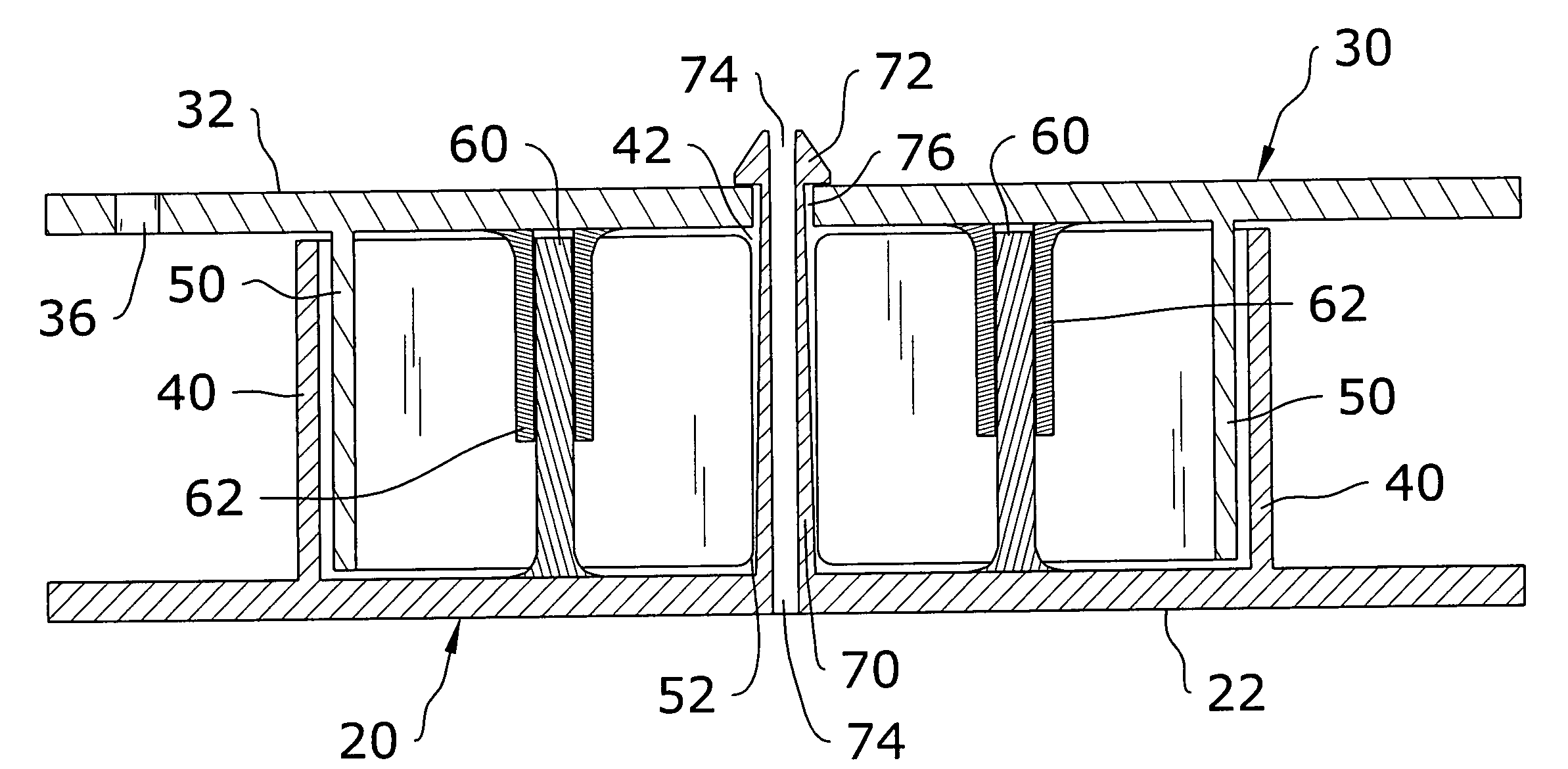
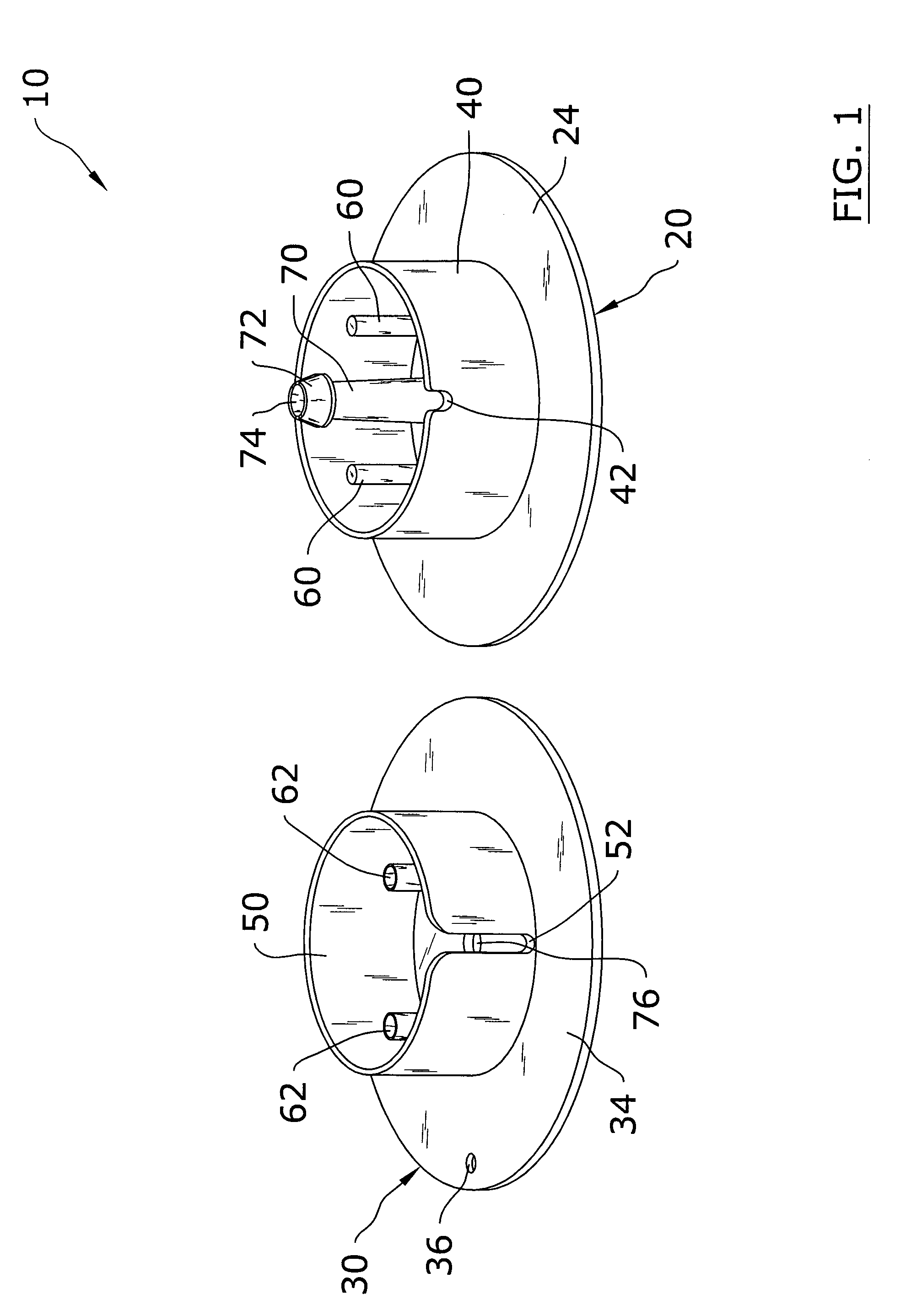
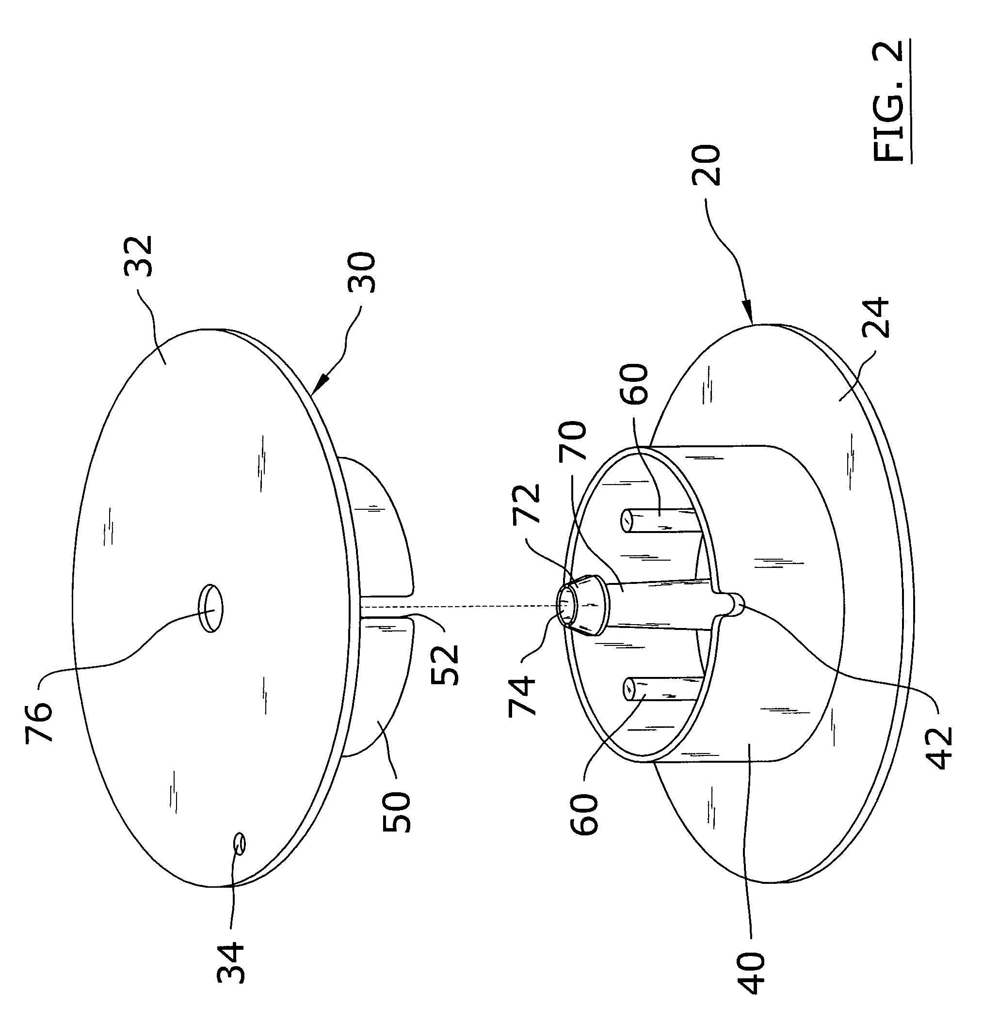
[0032]Turning now descriptively to the drawings, in which similar reference characters denote similar elements throughout the several views, FIGS. 1 through 8 illustrate a wire spooling system 10, which comprises a first spool member 20, having a tubular member 70 with a locking cap 72 and a first collar 40, and a second spool member 30, having an engagement aperture 76 and a second collar 50. The tubular member 70 extends through the first spool member 20 in direction substantially transverse to the first spool member 20. The locking cap 72 is positioned at the end of the tubular member 70 opposite the first spool member 20. The first collar 40 protrudes from the first spool member 20 in the same plane and direction as the tubular member 70. The second collar 50 of the second spool member 30 fits snugly within the first collar 40, wherein the first spool member 20 and second spool member 30 thereby form a spool shape. Upon fitting the first collar 40 and second collar 50...


PUM


Abstract

A wire spooling system for spooling and dispensing wire. The wire spooling system includes a first spool member, having a tubular member with a locking cap and first collar, and a second spool member, having an engagement aperture and second collar. The tubular member extends through the first spool member substantially transverse to the first spool member. The locking cap is positioned at the end of the tubular member opposite the first spool member. The first collar protrudes from the first spool member in the same plane and direction as the tubular member. The second collar protrudes from the second spool member and fits within the first collar. The spool members thereby form a spool shape. Upon fitting the second collar within the first collar, the engagement aperture receives the locking cap of the tubular member, securing the first spool member and second spool member in a locked position.

Description

CROSS REFERENCE TO RELATED APPLICATIONS[0001]Not applicable to this application.STATEMENT REGARDING FEDERALLY SPONSORED RESEARCH OR DEVELOPMENT[0002]Not applicable to this application.BACKGROUND OF THE INVENTION[0003]1. Field of the Invention[0004]The present invention relates generally to wire dispensing spool devices and more specifically it relates to a wire spooling system for efficiently spooling and dispensing previously unspooled wire.[0005]2. Description of the Related Art[0006]Wire dispensing spool devices have been in use for years. Typically, wire spools were only sold in large sizes with gigantic amounts of wire wound around the spool. These types of spools of wire were only usable with large equipment and were difficult to effectively manage and transport.[0007]More recently, wire spools came in smaller portions that were more manageable for smaller companies' needs for spooled wire. The smaller spools and lessened amounts of wire have proved a great help to smaller con...

Claims


Application Information

Patent Timeline
Patent Type & Authority Patents(United States)
IPC IPC(8): B65H75/14B65H75/18
CPCB65H75/14B65H75/50
Inventor LEA, FREDERICK L.
Owner LEA FREDERICK L
Why Eureka
Try Eureka