Al technical title is built by PatSnap Al team. It summarizes the technical point description of the patent document.
a technology for mounting systems and vehicles, applied in vehicles, vehicle components, tractor-trailer combinations, etc., can solve the problems of unmatched versatility of mounting systems for consumers
Inactive Publication Date: 2006-10-17
HORIZON GLOBAL AMERICAS INC
View PDF35 Cites 63 Cited by
Summary
Abstract
Description
Claims
Application Information
AI Technical Summary
This helps you quickly interpret patents by identifying the three key elements:
Problems solved by technology
Method used
Benefits of technology
[0005]In accordance with the purposes of the present invention as described herein, a vehicle accessory mounting system is provided. That vehicle accessory mounting system comprises a frame assembly having an opening and a locking cavity being in communication with the opening, at least one accessory mounting member capable of being removably mounted within the opening to removably mount an accessory to a vehicle. The accessory mounting member comprises a body, a locking element aperture within the body, and a locking element held within the aperture, the locking element being moveable between a retracted, unlocked position wherein the locking element does not engage the locking cavity and an extended, unlocked position wherein the locking element engages the locking cavity to prevent removal of the mounting member from within the opening.
Problems solved by technology
The mounting system also offers the consumer unparalleled versatility since one may mount a number of different vehicle accessories to the vehicle through the mounting system.
Method used
Image
Click on the blue label to locate the original text in one second.
Reading with bidirectional positioning of images and text.
Examples
Embodiment Construction
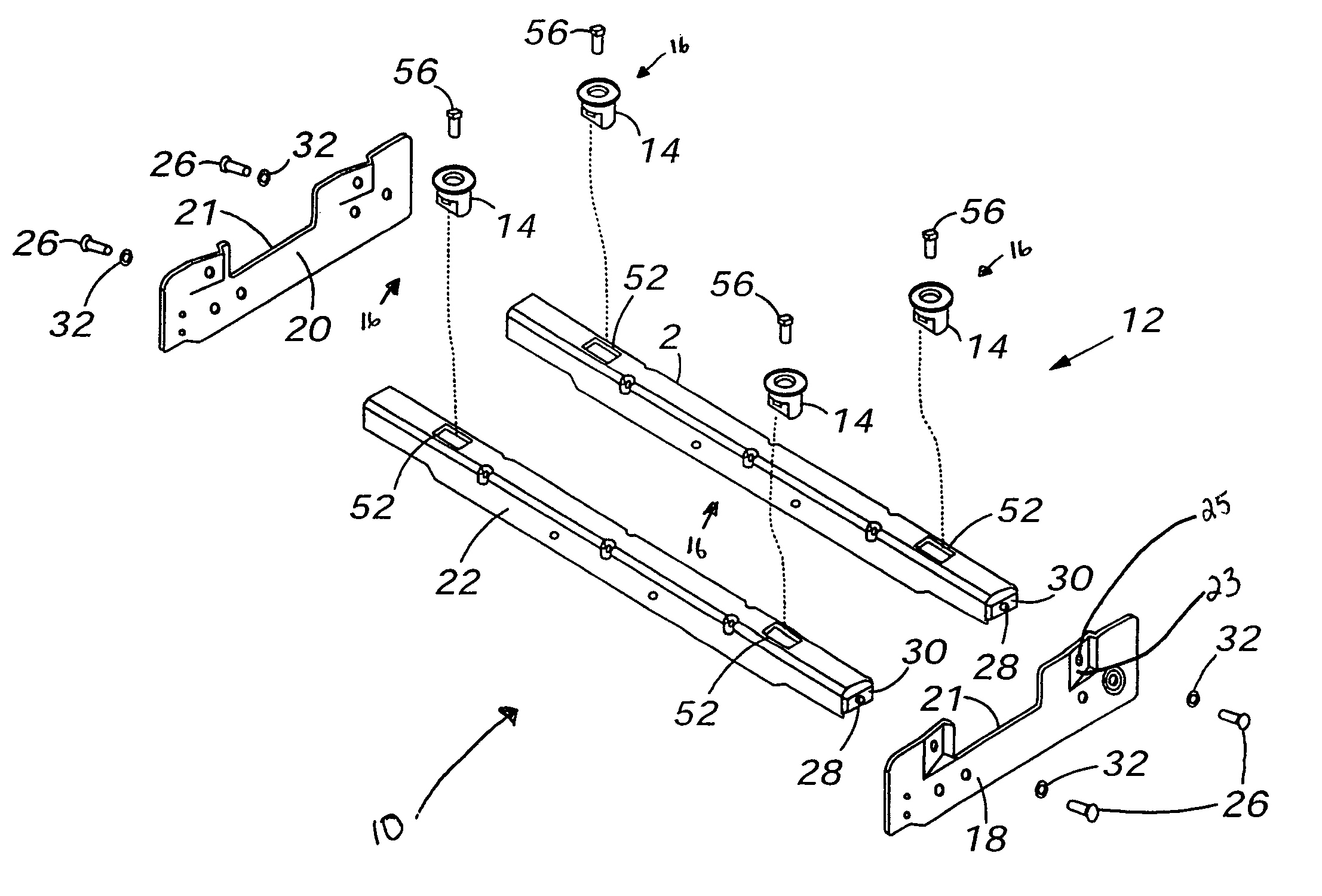
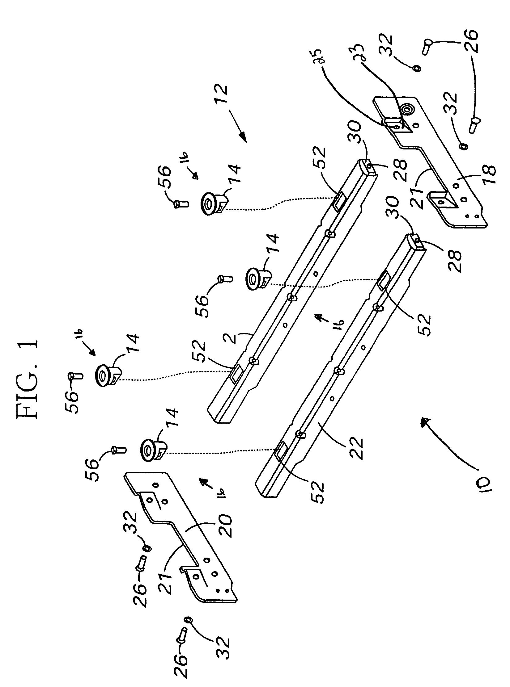
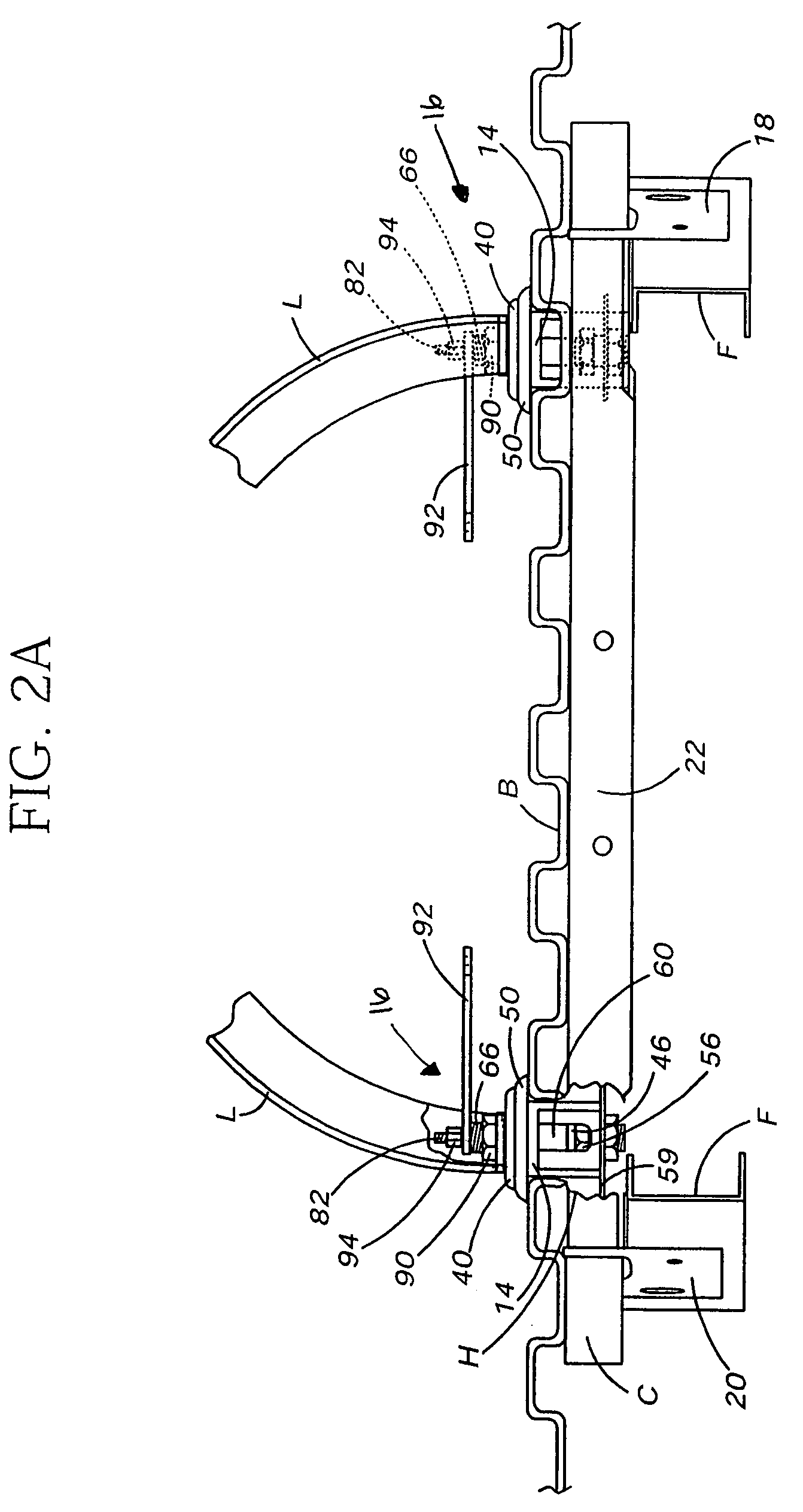
[0030]Reference is now made to FIGS. 1 and 2 illustrating the preferred embodiment of the vehicle accessory mounting system 10. The vehicle accessory mounting system 10 includes a frame assembly 12, at least one receptacle 14 carried by the frame assembly 12, and at least one accessory mounting member 16.
[0031]As best illustrated in FIGS. 1 and 2, the frame assembly 12 includes a first mounting bracket 18 and a second mounting bracket 20. The two mounting brackets 18, 20 are constructed from high strength material such as steel. They also may incorporate various notches and cutouts 21 to accommodate any vehicle channels C while allowing them to seat against the framework F of the vehicle to which the mounting system 10 is to be secured. First and second cross members 22, 24 extend between the first and second mounting brackets 18, 20. The cross members 22, 24 are also formed from high strength material such as tubular steel. The cross members 22, 24 are of a length sufficient to jus...
PUM
Abstract
Vehicle accessory mounting systems are limited in the accessories mountable thereto and interfere with the use of the bed. The present invention, however, is a vehicle accessory mounting system that comprises a frame assembly having an opening and a locking cavity being in communication with the opening, and at least one accessory mounting member capable of being removably mounted within the opening to removably mount an accessory to a vehicle. The accessory mounting member comprises a body, a locking element aperture within the body, and a locking element held within the aperture, the locking element being moveable between a retracted, unlocked position wherein the locking element does not engage the locking cavity and an extended, unlocked position wherein the locking element engages the locking cavity to prevent removal of the mounting member from within the opening.
Description
CROSS-REFERENCE TO RELATED APPLICATIONS[0001]This application claims priority from U.S. Provisional Patent Application No. 60 / 495,576 filed on Aug. 15, 2003, U.S. Provisional Patent Application No. 60 / 497,805 filed on Aug. 26, 2003, U.S. Provisional Patent Application No. 60 / 499,516 filed on Sep. 2, 2003, U.S. Provisional Patent Application No. 60 / 503,227 filed on Sep. 16, 2003, U.S. Provisional Patent Application No. 60 / 504,525 filed on Sep. 16, 2003, and a continuation-in-part of U.S. Utility patent application Ser. No. 10 / 465,773 filed on Jun. 19, 2003, which is a continuation-in-part of U.S. Utility patent application Ser. No. 10 / 189,641 filed on Jul. 3, 2002 now abandoned, wherein each of these applications are expressly incorporated by reference herein.TECHNICAL FIELD[0002]The present invention relates generally to the towing equipment field and, more particularly, to a system for mounting an accessory to a vehicle.BACKGROUND[0003]Over the years, various towing systems have be...
Claims
Application Information
Patent Timeline
Application Date:The date an application was filed.
Publication Date:The date a patent or application was officially published.
First Publication Date:The earliest publication date of a patent with the same application number.
Issue Date:Publication date of the patent grant document.
PCT Entry Date:The Entry date of PCT National Phase.
Estimated Expiry Date:The statutory expiry date of a patent right according to the Patent Law, and it is the longest term of protection that the patent right can achieve without the termination of the patent right due to other reasons(Term extension factor has been taken into account ).
Invalid Date:Actual expiry date is based on effective date or publication date of legal transaction data of invalid patent.
Patent Type & Authority Patents(United States)
IPC IPC(8): B60J3/00B62D53/08
CPCB62D53/08
Inventor LINDENMAN, THOMAS W.MCCOY, RICHARD W.ROBERTS, ANTHONY S.