Illumination apparatus

a technology of a machine and a body, which is applied in the direction of electric lighting with batteries, lighting support devices, electric circuit arrangements, etc., can solve the problems of reducing size, weight and energy, and avoiding the use of another light sour

Inactive Publication Date: 2006-10-17
CATEYE
View PDF10 Cites 77 Cited by
  • Summary
  • Abstract
  • Description
  • Claims
  • Application Information

AI Technical Summary

Benefits of technology

[0010]An object of the present invention is to provide an illumination apparatus, not restricted to application to a bicycle, that can achieve light distribution towards the front, and light illumination in a direction other than the front direction, without using a light source other than the light source for frontward illumination.
[0012]By the structure set forth above, illumination in the frontward direction and illumination in the sideward direction can be achieved by a simple configuration using only the light emitting diode for forward illumination, dispensable of another light source for the sideward direction.
[0013]By using the illumination apparatus of the present invention, application of the illumination apparatus is not limited to bicycles, and illumination in the frontward direction and illumination around the illumination side region can be achieved without using a light source other than the light source for forward illumination. Thus, the size, weight, energy and cost can be reduced.

Problems solved by technology

However, use of another light source is not preferable from the standpoint of reducing the size, weight and energy, as well as the fabrication cost.

Method used


Image

  • Illumination apparatus
  • Illumination apparatus
  • Illumination apparatus

Examples


Embodiment Construction

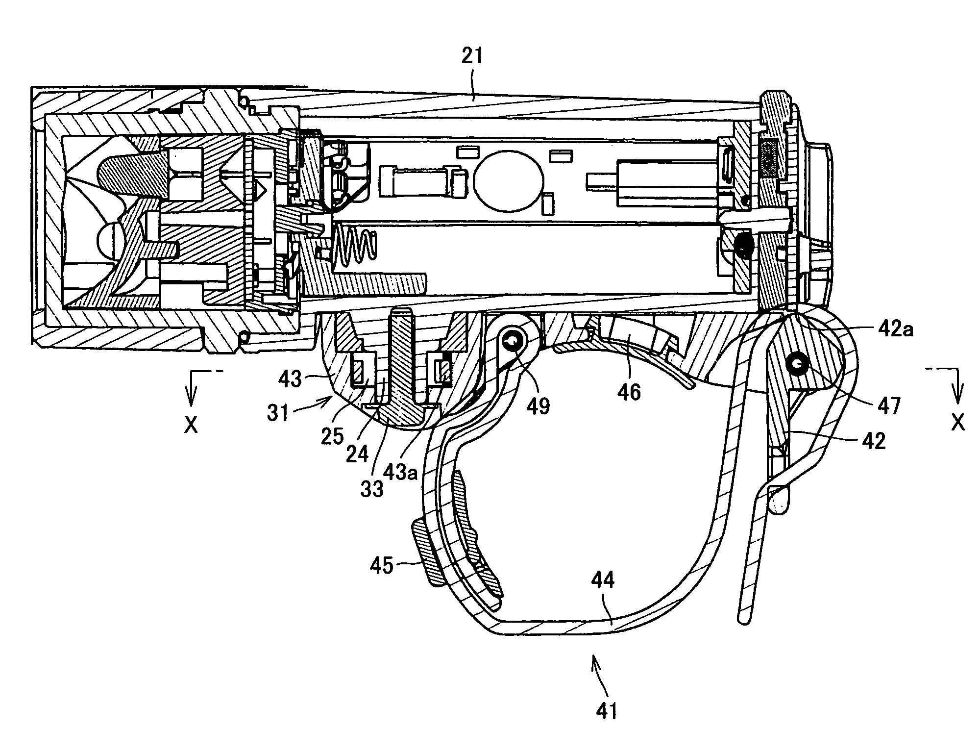
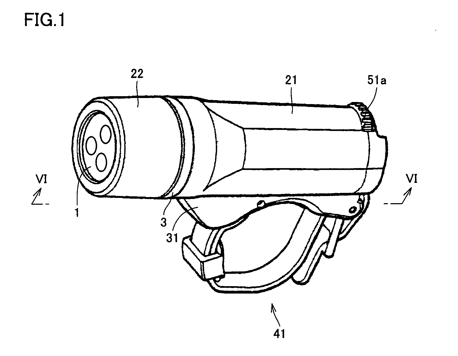
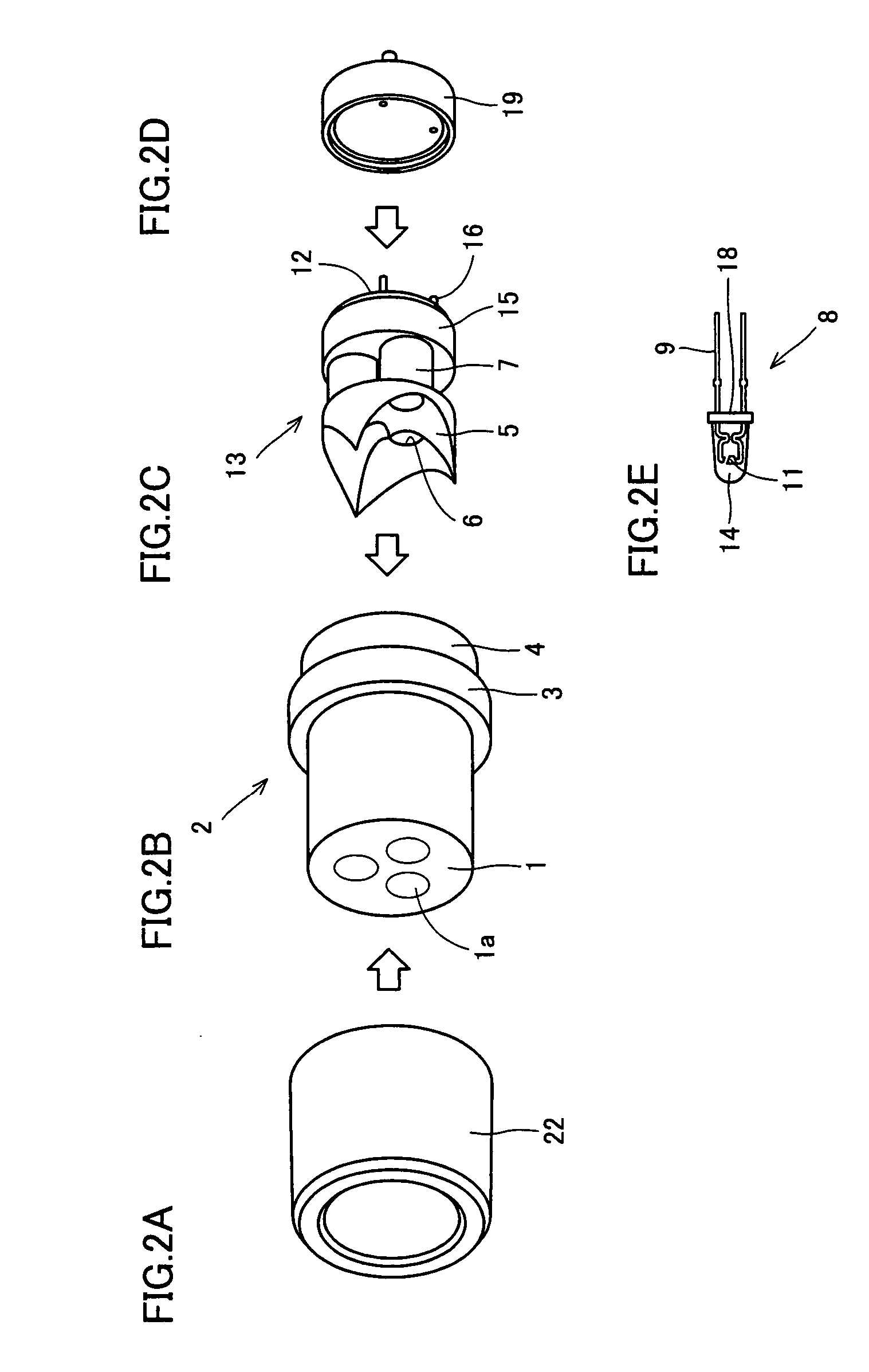
[0026]An embodiment of the present invention will be described hereinafter with reference to the drawings. Referring to FIG. 1, an illumination apparatus of the present embodiment includes a front projection window 1 projecting light frontward, a front side cover 22 covering the side region, and a casing 21 located at the rear of cover 22 to accommodate components of the illumination apparatus. A side transmission unit 3 transmitting light from the side circumferential region is arranged between front side cover 22 and casing 21. Although not shown, light emitting diode is employed for the light source. A battery accommodated in casing 21 is employed as a power supply thereof.

[0027]A flat portion 21a is provided at the side area of casing 21. A support member 31 to support the illumination apparatus is attached to flat region 21a. The flat portion of the casing may be a bottom 21a. A fixture band 41 is attached to support member 31. Fixture band 41 fastens the illumination apparatus...


PUM


Abstract

An illumination apparatus is provided that can achieve light distribution towards the front, and light illumination in a direction other than the front direction, without using a light source other than the light source for frontward illumination. The illumination apparatus includes a light emitting diode located at the front side of the illumination apparatus, corresponding to one end, a side transmission unit having a surface exposed at a gap in the casing, located rearward of the light emitting diode to transmit light from the side, and a light path modification unit, located rearward of the light emitting diode to modify the direction of light output from the light emitting diode towards the side transmission unit.

Description

BACKGROUND OF THE INVENTION[0001]1. Field of the Invention[0002]The present invention relates to illumination apparatuses, and more particularly, to an illumination apparatus employing LED (Light Emitting Diode).[0003]2. Description of Related Art[0004]The lighting apparatus attached to a bicycle must ensure favorable field of view in the frontward direction while suppressing excessive glare with respect to vehicles coming from the opposite direction. A conventional illumination apparatus is implemented as set forth below.[0005](a) The light emitted from the filament arranged in the proximity of the focal point of the parabolic mirror diverges in all directions. All the light other than the light emitted directly frontward is reflected at the parabolic mirror to form frontward parallel light rays. These light rays are set to form a predetermined light distribution by the front lens together with the light directly output frontward (for example, refer to Japanese Patent Laying-Open N...

Claims


Application Information

Patent Timeline
Patent Type & Authority Patents(United States)
IPC IPC(8): F21L4/04F21V21/08F21V23/04F21V7/04F21L4/02B62J6/02F21L4/00F21S2/00F21S8/10F21V8/00F21V11/00F21V13/00F21V13/04F21V14/00F21W107/13F21Y101/02
CPCB62J6/02F21L4/02F21Y2101/02B62J6/029B62J6/03F21Y2115/10
Inventor FUJIMOTO, TAKUYA
Owner CATEYE
Why Eureka
Try Eureka