Placing printing elements and mark sensor at proper positions with respect to the cutter member

Inactive Publication Date: 2006-10-17
BROTHER KOGYO KK
View PDF21 Cites 116 Cited by
  • Summary
  • Abstract
  • Description
  • Claims
  • Application Information

AI Technical Summary

Benefits of technology

[0008]To achieve the aforementioned objects, in accordance with another aspect of the present invention, there is provided a tape printing device for printing on a long tape. The long tape is a label tape including a plurality of labels temporarily stuck on a front side of a long strippable sheet being aligned along the length of the strippable sheet and a plurality of position indication marks formed on a back side of the strippable sheet along its length to be opposed to (i.e. to face via the strippable sheet) corresponding labels respectively for enabling detection of each label on the front side. Each position indication mark corresponding to each label on the front side is formed at a position on the back side of the strippable sheet that corresponds to a prescribed position on the corresponding label in a tape feeding direction. The tape printing device comprises a tape feed unit for feeding the long tape, a printing unit for printing on the tape, a cutter member being placed on the downstream side of the printing unit in the tape feeding direction for cutting the tape, a mark sensor which successively detects the position indication marks formed on the long tape when the tape is fed, and a control unit which carries out printing by controlling the printing unit while controlling the tape feed unit based on an output signal outputted by the mark sensor. The printing unit is placed so that the printing unit, at a point when the label tape after the printing on a label has been fed by the control unit to a tape cutting position to be cut by the cutter member, will be situated on the downstream side in the feeding direction of a print start position of a label nearest to the tape cutting position. The mark sensor is placed so that the mark sensor, at the point when the label tape after the printing on a label has been fed by the control unit to the tape cutting position to be cut by the cutter member, will be situated on the downstream side in the feeding direction of a position indication mark corresponding to the label nearest to the tape cutting position and on the upstream side in the feeding direction of the printing unit.

Problems solved by technology

However, in the aforementioned conventional printing devices capable of printing on label tapes, if the mark sensor is placed far from a thermal head, restarting the tape printing device after shutting off the power might result in feeding the first label without printing and starting the printing from the second label in cases where the space (interval) between adjacent labels is short.

Method used


Image

  • Placing printing elements and mark sensor at proper positions with respect to the cutter member
  • Placing printing elements and mark sensor at proper positions with respect to the cutter member
  • Placing printing elements and mark sensor at proper positions with respect to the cutter member

Examples


Embodiment Construction

,

[0018]Referring now to the drawings, a description will be given in detail of an embodiment of a tape printing device and a tape cassette in accordance with the present invention. First, a brief outline of the composition of the tape printing device of the embodiment will be described referring to FIGS. 1 through 4.

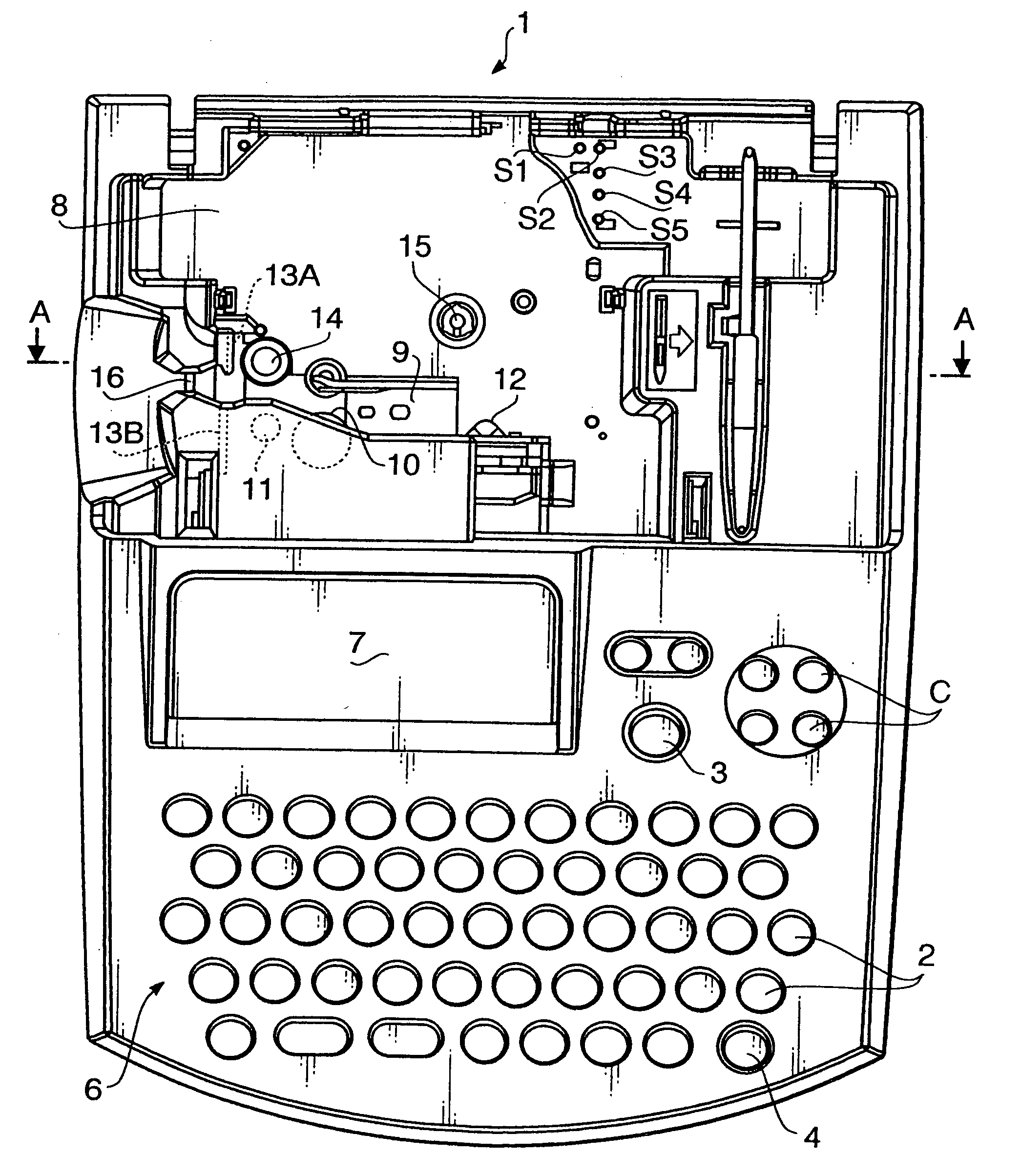
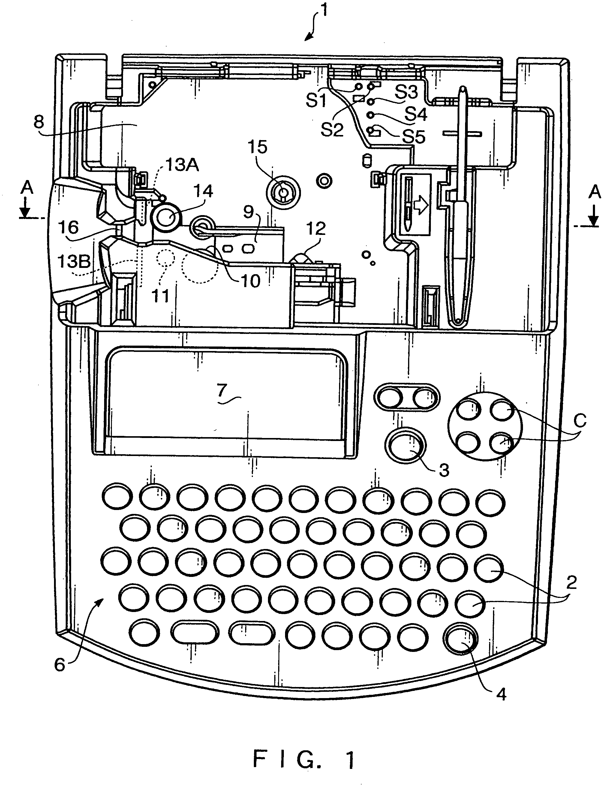
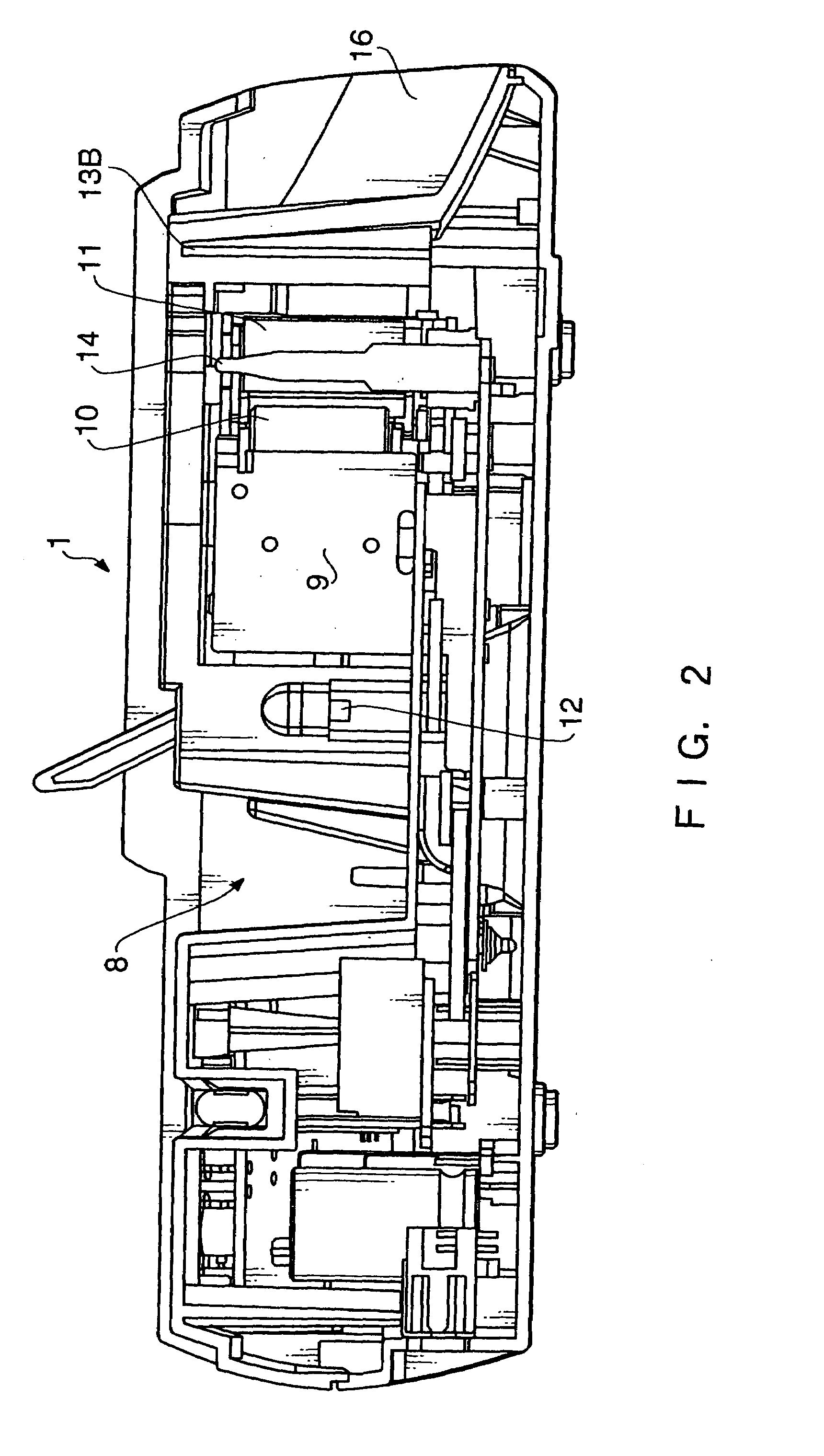
[0019]FIG. 1 is a schematic top view of the tape printing device in accordance with the embodiment with its storage cover removed. FIG. 2 is a cross-sectional view of the tape printing device of the embodiment taken along the line A—A shown in FIG. 1. FIG. 3 is a schematic diagram showing a brief outline of the composition of a thermal head of the tape printing device of the embodiment, in which (A) is a plan view and (B) is a front view. FIG. 4 is a block diagram showing the composition of a control system of the tape printing device of the embodiment.

[0020]As shown in FIGS. 1 and 2, the tape printing device 1 includes a keyboard 6 on which various key boards are arrang...


PUM

PropertyMeasurementUnit
widthaaaaaaaaaa
lengthaaaaaaaaaa
distanceaaaaaaaaaa

Abstract

A tape printer, wherein when a label tape (36) is fed to a tape cutting position after the label (39) of the label tape (36) is printed out, the heating elements (R1 to Rn) of a thermal head (9) are disposed so as to be opposed to the position of a next printed label (39) slightly on the upstream side of a label head position on the downstream side of thereof in the feeding direction and to be opposed to the position of the next printed label (39) on the downstream side of the printing start position thereof (so that a<b can be established in FIG. 7), and a mark detection sensor (12)is disposed on the upstream side of the heating elements (R1 to Rn) so as to be opposed to the position slightly on the downstream side of the position opposed to a position detection mark (39B) (so that c<e can be established in FIG. 7).

Description

TECHNICAL FIELD[0001]The present invention relates to a tape printing device configured to have the function of printing letters, etc. on a long tape while feeding the tape and thereafter cutting off the printed tape by a cutter member, and a tape cassette which is detachably loaded in the tape printing device. In particular, the present invention relates to the composition of a tape printing device and a tape cassette for using a label tape in which a plurality of labels are temporarily stuck on the front side of a long strippable sheet being aligned along the length of the strippable sheet and position indication marks for the detection of the positions of the labels are formed at prescribed positions on the back side of the strippable sheet.BACKGROUND OF THE INVENTION[0002]Tape printing devices for printing letters, etc. on a label tape (having a plurality of labels temporarily stuck on the front side of a long strippable sheet being aligned along its length) are well known today...

Claims


Application Information

Patent Timeline
Patent Type & Authority Patents(United States)
IPC IPC(8): B41J11/26B23K11/00B23K11/14B41J3/36B41J3/407B41J11/00B41J11/42B41J11/46B41J11/66B41J11/70B41J15/04
CPCB41J3/4075B41J11/009B41J11/0095B41J11/46B41J11/703B41J15/044
Inventor HARADA, HIRONORINONOMURA, YOSHIHITO
Owner BROTHER KOGYO KK
Why Eureka
Try Eureka