Driving separation distance indicator

a technology of driving separation distance and indicator, which is applied in the direction of braking system, using reradiation, instruments, etc., can solve the problems of not helping reduce the driver's reaction time or vehicle braking rate, and accidents that are catastrophic or even fatal,

Active Publication Date: 2006-10-17
DONNELLY CORP
View PDF62 Cites 446 Cited by
  • Summary
  • Abstract
  • Description
  • Claims
  • Application Information

AI Technical Summary

Problems solved by technology

Drivers which allow an insufficient distance between their vehicle and the vehicle ahead of their vehicle may cause a traffic accident if the leading vehicle suddenly slows down.
This error in judgment of a safe separation distance appears to increase at higher speeds, often resulting in catastrophic or even fatal accidents.
However, this does not help reduce the driver's reaction times or vehicle braking rates.
Many of these factors may also affect the ability of the driver of the following vehicle to control the vehicle path under severe braking conditions, which often results in an increase in the damage caused during this type of accident.
However, the driver's inability to retain this advice, relate the advice to a particular traffic condition at any time, and adhere to the advice is one of the causes of the type of accident described above.
First, whether the separation distance behind a leading vehicle is sufficient, and second, whether a following vehicle is too close to be able to react safely in the event of an emergency.
However, rearward separation is the responsibility of the driver of the following vehicle and is generally not under the control of the driver of the leading vehicle.
However, it is not uncommon, if a driver is threatened by the closeness of a following vehicle, for the driver of the leading vehicle to tap the brake pedal in order to illuminate the vehicle brake lights, thus causing the following driver to brake and increase the separation distance between the vehicles.

Method used


Image

  • Driving separation distance indicator
  • Driving separation distance indicator

Examples


Embodiment Construction

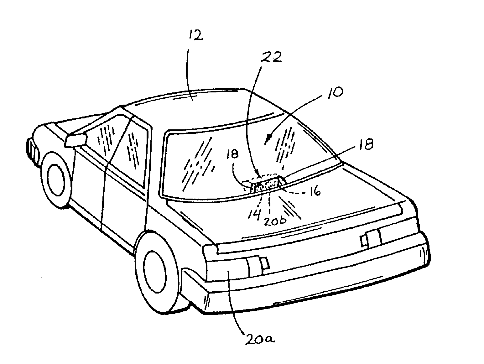
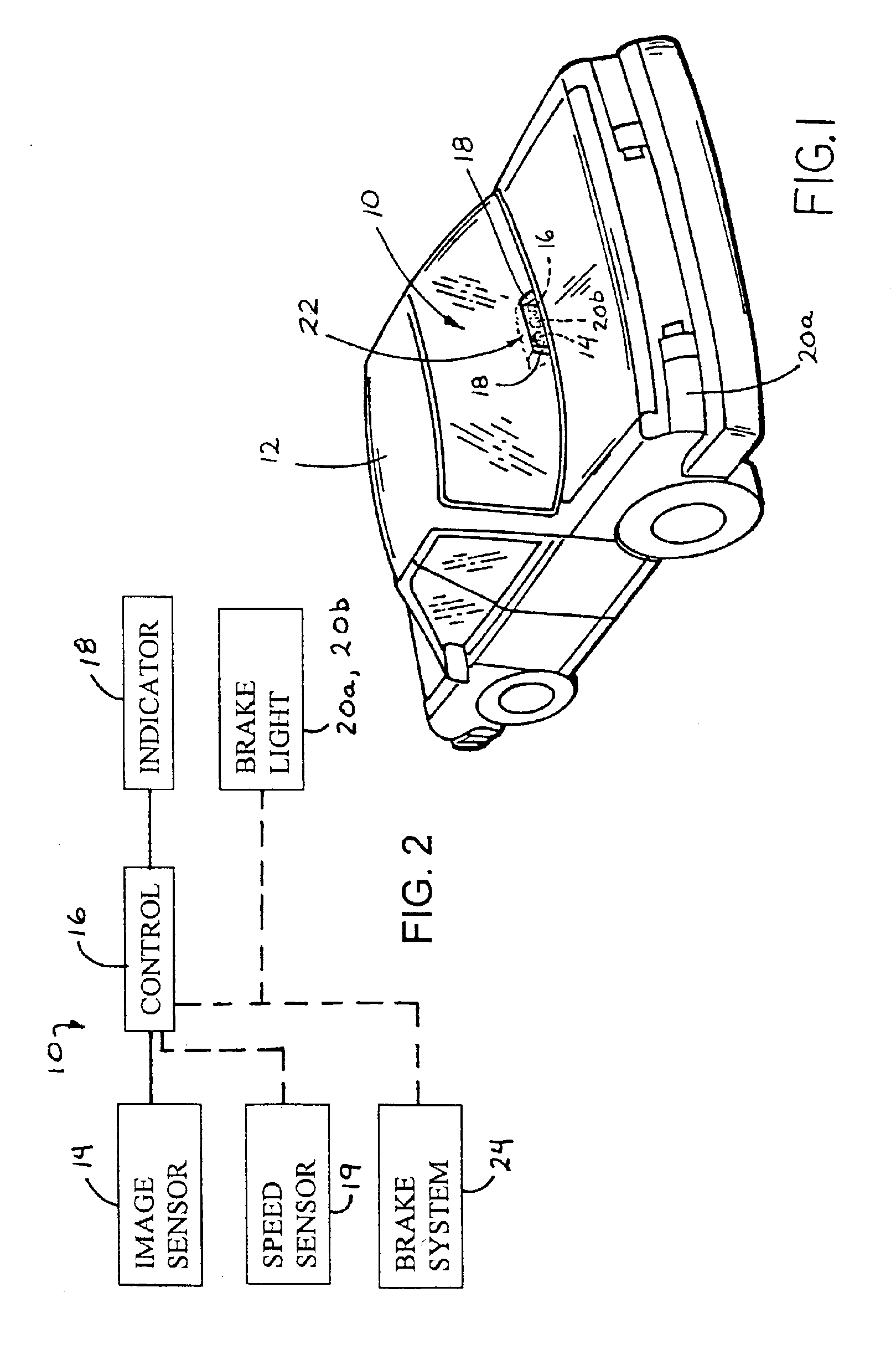
[0017]Referring now to the drawings and the illustrative embodiment depicted therein, a driving separation warning or indication system 10 is mounted at a vehicle 12 and is operable to provide a warning, indication or alert to a driver of a following vehicle that the following vehicle is within a threshold separation distance or interspacing distance or following distance from the subject vehicle 12 (FIG. 1). The driving separation warning system 10 includes an imaging sensor 14, a control 16 and an indicator 18 (FIGS. 1 and 2). The control 16 is operable to at least occasionally activate the indicator in response to a signal or image from the imaging sensor and a threshold separation distance. The indicator may be viewable by the driver of the other vehicle and thus may alert the driver that he or she is traveling too close to the subject vehicle. The threshold separation or interspacing distance may be substantially continuously calculated or otherwise determined at least in respo...


PUM


Abstract

A driving separation indication system for a vehicle includes an imaging sensor, a control and at least one indicator. The control is operable to process an image captured by the imaging sensor representative of a scene occurring exteriorly of the subject vehicle and to detect another vehicle via processing of the image. The control is operable to determine a threshold interspacing distance in response to a speed of the subject vehicle, and is operable to determine a distance from the subject vehicle to the detected other vehicle. The control is operable to at least occasionally actuate the indicator in response to the distance from the subject vehicle to the other vehicle being less than or equal to the threshold interspacing distance. The control may generally continuously determine the speed of the vehicle and the threshold interspacing distance to provide an appropriate threshold interspacing distance.

Description

CROSS REFERENCE TO RELATED APPLICATION[0001]The present application claims priority of U.S. provisional application, Ser. No. 60 / 375,524, filed Apr. 25, 2002 by Schofield, which is hereby incorporated herein by reference in its entirety.FIELD OF THE INVENTION[0002]The present invention relates generally to a warning or indicating system for a vehicle and, more particularly, to a warning system which is operable to alert a driver of a following vehicle that the following vehicle is within a threshold separation distance of the subject vehicle.BACKGROUND OF THE INVENTION[0003]Drivers which allow an insufficient distance between their vehicle and the vehicle ahead of their vehicle may cause a traffic accident if the leading vehicle suddenly slows down. In the event of the driver of the leading vehicle responding to a situation with hard braking, the driver of the following vehicle may have insufficient time to notice and react to the illumination of the leading vehicle's brake lights, ...

Claims


Application Information

Patent Timeline
Patent Type & Authority Patents(United States)
IPC IPC(8): G08G1/017B60Q1/30B60Q1/52G01S11/12
CPCB60Q1/302B60Q1/525B60T2201/08B60T2201/082G01S11/12B60Q1/50B60Q1/535
Inventor SCHOFIELD, KENNETH
Owner DONNELLY CORP
Why Eureka
Try Eureka