FM-CW radar apparatus

a radar and cw technology, applied in the direction of antennas, instruments, movable body antenna adaptation, etc., can solve the problems of difficult to obtain accurate height information, and it is not possible to clearly identify whether it is really an overbridge or a vehicle traveling ahead

Active Publication Date: 2006-10-17
FUJITSU GENERAL LTD
View PDF31 Cites 8 Cited by
  • Summary
  • Abstract
  • Description
  • Claims
  • Application Information

AI Technical Summary

Benefits of technology

[0009]It is an object of the present invention to provide an FM-CW radar apparatus that can detect a stationary object, in particular, an overbridge, located above the road ahead in a simple manner.
[0013]According to the present invention, as the projection angle of the beam pattern can be varied in the upward direction as described above, an overbridge can be detected without tilting the radar head sensor or the antenna upward and they can be kept stationary.

Problems solved by technology

With a conventional radar, however, as the beam is scanned in lateral directions as described above, it is difficult to obtain accurate height information.
As a result, when an overbridge, that is, a structure such as a bridge over the road ahead, is detected, it may not be possible to clearly identify whether it is really an overbridge or a vehicle traveling ahead.

Method used


Image

  • FM-CW radar apparatus
  • FM-CW radar apparatus
  • FM-CW radar apparatus

Examples


embodiment 1

[0053

[0054]FIG. 7 is a diagram showing a method for forming a radar beam pattern according to the radar apparatus of the present invention. As shown, according to the radar apparatus of the present invention, the beam pattern can be formed directed obliquely upward without tilting the radar sensor head or the antenna. In the present invention, the projection angle of the beam pattern can be varied not only in the upward direction but also in the downward direction.

[0055]FIG. 8 is a diagram showing the configuration of a traveling wave antenna used in the present invention. According to the radar apparatus of the present invention, when this antenna is used as the transmitting antenna of the FM-CW radar apparatus shown in FIG. 3 or 4, for example, the projection angle of the radar beam pattern can be varied in upward / downward directions by varying the tilt angle θ of the combined beam pattern (BP) radiated from the antenna, without varying the mounting angle of the radar sensor head ...

embodiment 2

[0064

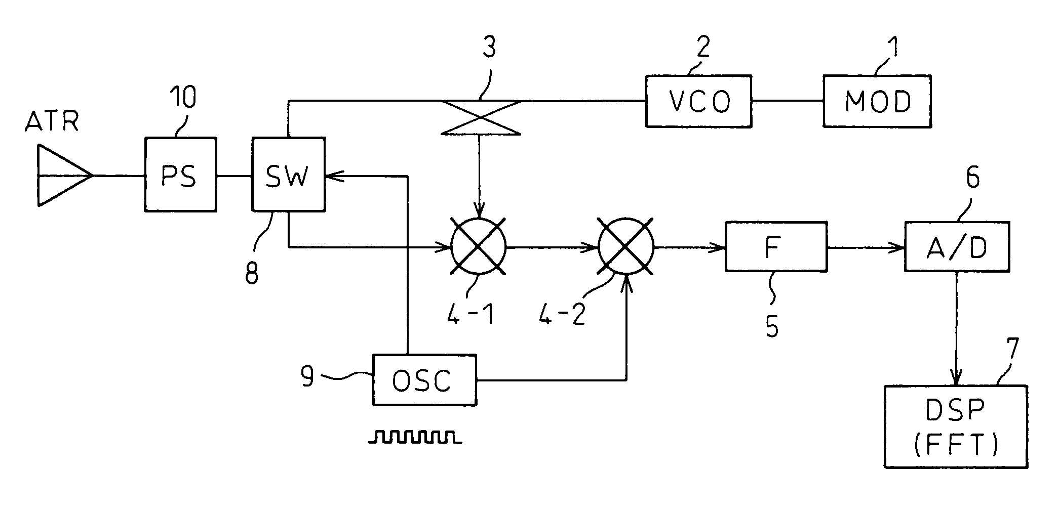
[0065]FIG. 12 is a diagram showing one configuration example of a two-antenna FM-CW radar according to the present invention. The difference from the configuration shown in FIG. 3 is the inclusion of a phase shifter 10 which is provided between the receiving antenna AR and the mixer 4. Here, the phase shifter may be provided between the transmitting antenna AT and the directional coupler 3.

[0066]In the two-antenna radar apparatus shown in FIG. 12, the phase of the radio wave to be transmitted or received is controlled by the phase shifter PS provided on either the transmitting or receiving side, and in this way, the projection angle of the beam pattern can be varied in upward / downward directions while holding the antenna stationary. According to the present invention, an overbridge can be detected by varying the projection angle of the beam pattern in upward / downward directions while holding the antenna stationary.

[0067]FIG. 13 is a diagram showing one configuration example of ...


PUM


Abstract

An FM-CW radar apparatus capable of detecting a stationary object, in particular, an overbridge, located above the road ahead in a simple manner uses a traveling wave antenna as a transmitting antenna, and includes a means for varying, in upward and downward directions the projection angle of a combined beam pattern of a transmitted wave radiated from the traveling wave antenna, and an overbridge is detected by varying the projection angle of the combined beam pattern in the upward direction using the varying means. Further, a phase shifter for varying the projection angle of the beam pattern in upward / downward directions by controlling the phase of the radio wave to be transmitted or received is provided on either a transmitting antenna or a receiving antenna or on a transmitting / receiving antenna, and an overbridge is detected by controlling the phase shifter and varying the projection angle of the beam pattern in the upward direction.

Description

[0001]Applicant claims the right to priority based on Japanese Patent Application No. 2003-12175, filed Jan. 21, 2003.BACKGROUND OF THE INVENTION[0002]1. Field of the Invention[0003]The present invention relates to an FM-CW radar apparatus that uses a frequency-modulated (FM) continuous wave (CW) as a signal for transmission and, more particularly, to an FM-CW radar apparatus that can detect an overbridge, that is, a stationary object such as a bridge, a road sign, a billboard, or the like, located above the road ahead or on the roadside.[0004]2. Description of the Related Art[0005]A scanning radar scans a given area by turning the radar in lateral directions with very fine step angles within a predetermined time. At each step angle, a radar beam is projected from the radar-equipped vehicle toward a vehicle traveling on the road ahead, and the wave reflected from the vehicle ahead is received; the reflected wave thus received is processed to detect the presence of a vehicle ahead an...

Claims


Application Information

Patent Timeline
Patent Type & Authority Patents(United States)
IPC IPC(8): G01S13/93G01S7/35G01S13/34G01S13/58G01S13/931H01Q1/32H01Q3/22
CPCG01S7/35G01S13/345G01S13/584G01S13/931H01Q1/3233H01Q3/22
Inventor SHOUNO, MASAYOSHIHITOTSUYA, MASAKI
Owner FUJITSU GENERAL LTD
Why Eureka
Try Eureka