
Buckle device

Inactive Publication Date: 2006-10-24
ASHIMORI INDS
View PDF27 Cites 12 Cited by
  • Summary
  • Abstract
  • Description
  • Claims
  • Application Information

AI Technical Summary

Benefits of technology

[0017]Furthermore, in the buckle device described in JP, U, 6-66311, when the inertial body moves to the lock lever side upon a sudden stop of the buckle body, the lock pin may move very fast to the second position since the whole inertial force acting on the lock pin acts to move the lock pin to the second position. That is, since the lock lever may pivot very fast to the non-locked position side, the inertial body, which starts moving upon a sudden stop of the buckle body, may not contact with the lock lever appropriately and thus there is a high possibility that the lock lever is not prevented from pivoting to the non-locked position.
[0065]In this buckle device, the second lever is pushed to pivot to the lock position by the first lever which is pivoted by an inertial force just after the buckle body has started moving, and then the second lever is held in the lock position side by an inertial force when the buckle body comes into an abrupt stop. That is, when the buckle body stops abruptly, the lock bar moves to the second position thereby restraining the second lever from pivoting from the lock position to the non-lock position more securely, and thus it is possible to securely prevent the detachment of the tongue plate from the buckle body.

Problems solved by technology

The buckle device described in JP, U, 6-66315 has a problem in that upon inserting the tongue plate, a sharp impact noise is generated by a collision between the metal lock pin and the metal frame when the lock pin is moved to the first position by the urging force of a biasing member and is received by the ends of the pair of long holes.
Moreover, in this buckle device, since a pin member like a round bar is used as the lock pin, a plastic lock pin holder with a complex structure needs to be provided to hold the lock pin, and thereby the number of parts is increased, the structure becomes more complicated, and also assembly of the buckle device becomes inconvenient.
This buckle device is provided with a coil spring member for urging the release button in the same direction as the detachment direction of the tongue plate in addition to a spring member for urging the ejector in the detachment direction of the tongue plate, and therefore a pair of spring receiving parts to receive the coil spring member as well as the coil spring member need to be provided, and thereby the number of parts is increased, the structure becomes complicated, and also the assembly of the buckle device becomes inconvenient.
However, when the buckle body comes to a sudden stop, an inertial force acts on the lock pin as well, and since the lock pin is received directly by the lock lever, a large force is exerted on the lock lever by the lock pin.

Method used


Image

  • Buckle device
  • Buckle device
  • Buckle device

Examples


Embodiment Construction

[0123]The embodiments of the first invention of the present application will be described referring to the drawings.

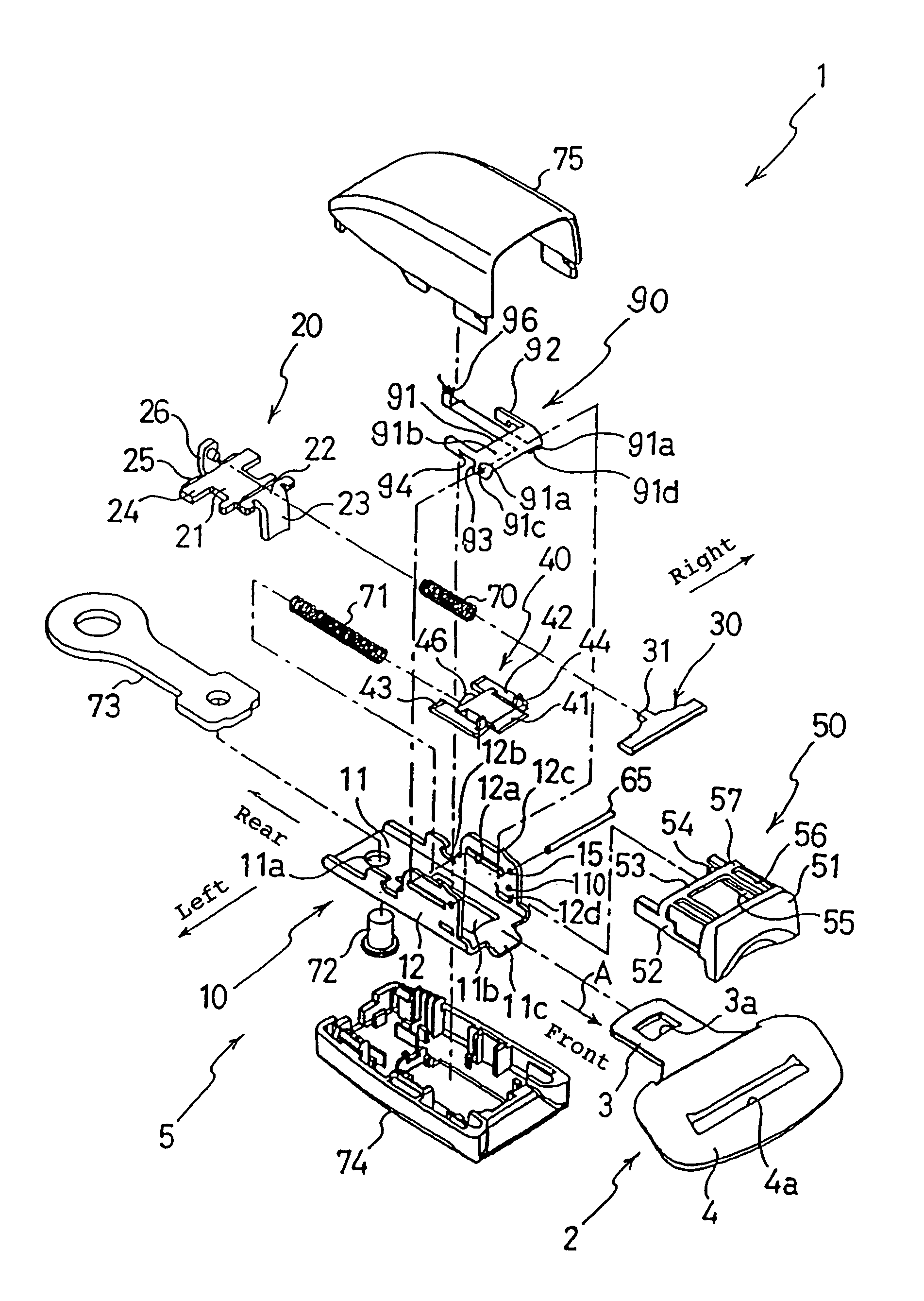
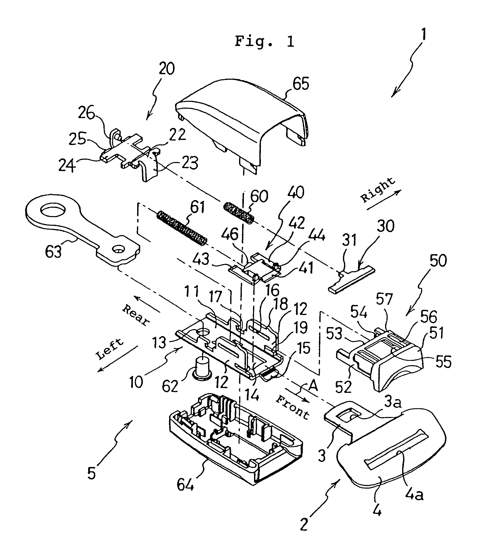
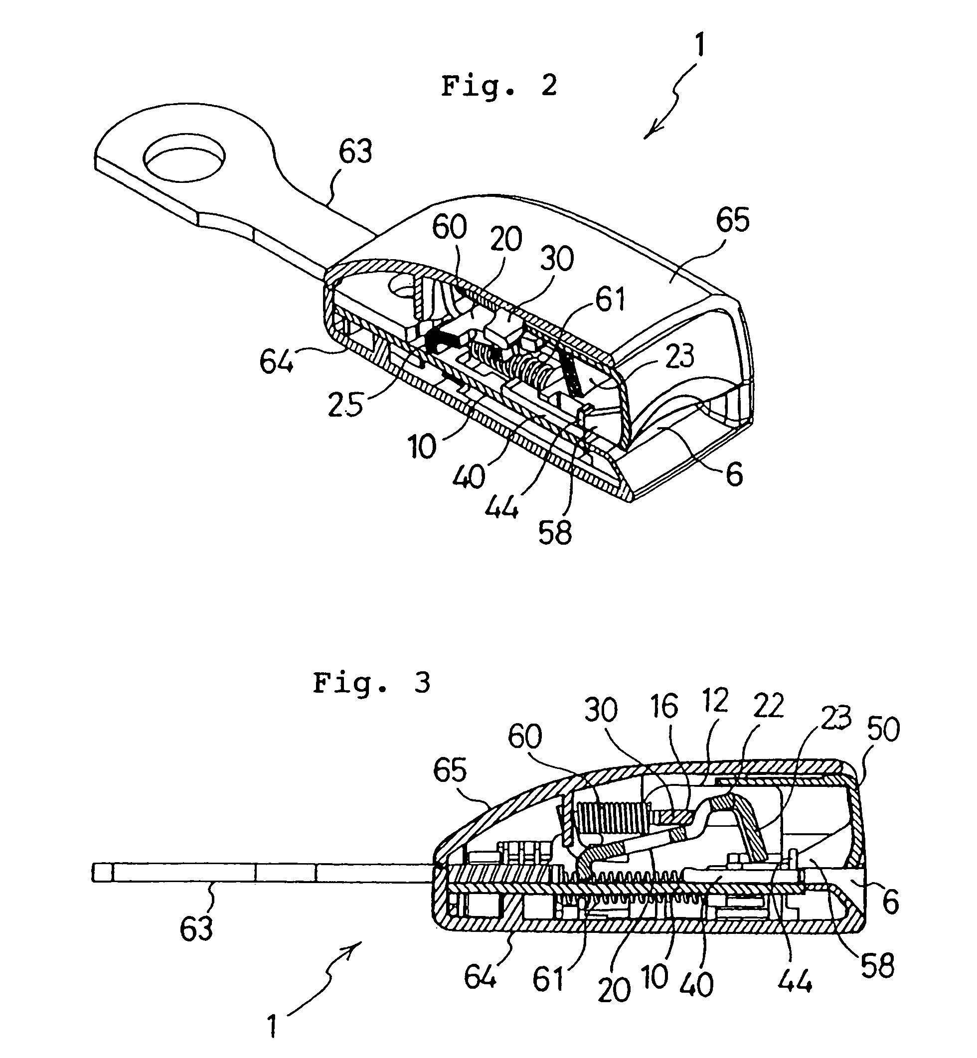
[0124]A seat belt apparatus of a vehicle is equipped with a buckle device for connecting a webbing worn by the occupant to the vehicle body. By way of explanation, the buckle device 1 shown in FIGS. 1 to 7 will be explained by defining the four directions: forward / rearward and rightward / leftward as shown in FIG. 1 where arrow A denotes the forward direction. The buckle device 1 basically consists of a tongue plate 2 which is movably attached to intermediate part of the webbing (not shown) and a buckle body 5, and the front end part of the buckle body 5 is provided with an insert port 6 for inserting the tongue plate 2. The tongue plate 2 has a tongue part 3 made of metal and to be inserted into the buckle body 5 and a tongue body part 4 integrally formed with the tongue part 3 and covered with a plastic material, and the tongue part 3 is formed with a rectangular engag...


PUM


Abstract

A buckle device capable of reducing an impact noise generated when a tongue plate (2) is inserted and eliminating a coil spring member energizing a release button (50) and a lock pin holder so as to simplify a structure, wherein a lock bar (30) has both end parts inserted into slots (16) and is mounted on a pair of side plate parts (12), both end parts of the lock bar (30) are engaged with a pair of guide grooves (54) in a pair of guide wall parts (52) of a synthetic resin release button (50) and, when the tongue plate (2) is inserted, the lock bar (30) is moved rapidly to the front end part of the slots (16) and, in this case, the end parts of the lock bar (30) are supported on a supporting part (55) at the end of the guide groove (54), not on the end of the slots (16).

Description

RELATED APPLICATIONS[0001]This application is a divisional application of U.S. patent application Ser. No.: 10 / 049,400, filed Jun. 7, 2002, now U.S. Pat. No. 6,701,587 which is the National Stage of International Application No. PCT / JP00 / 05435, filed Aug. 14, 2000, each of which are herein incorporated by reference in their respective entireties.TECHNICAL FIELD[0002]The present invention relates to a buckle device for use in seat belts of motor vehicles, and particularly relates to a buckle device in which impact noises between metal members upon insertion of a tongue plate are reduced and of which structure is simplified. The present invention further relates to a buckle device including a buckle body and a tongue plate, and particularly relates to a buckle device which has an improved structure to prevent detachment of the tongue plate from the buckle body in an emergency of the vehicle, and to a buckle device which is configured to prevent detachment of the tongue plate from the ...

Claims


Application Information

Patent Timeline
IPC IPC(8): A44B11/26A44B11/25
CPCA44B11/2523Y10T24/4567Y10T24/45665Y10T24/45639Y10T24/45623A44B11/24
Inventor SATO, AKIRAYAMADA, NAOHIRO
Owner ASHIMORI INDS
Learn More