Clamp assembly for hydroforming die

a technology of hydroforming die and clamping plate, which is applied in the field of hydroforming, can solve the problems of large press size, large hydraulic press size, and inability to generate enough force to simultaneously hydroform, and achieve the effects of reducing initial capital expenditure, enduring extremely high forces, and less expensive hydraulic systems

Inactive Publication Date: 2006-10-24
GM GLOBAL TECH OPERATIONS LLC
View PDF10 Cites 12 Cited by
  • Summary
  • Abstract
  • Description
  • Claims
  • Application Information

AI Technical Summary

Benefits of technology

[0007]One advantage of the present invention is that a clamp assembly is provided for a hydroforming die that has the ability to withstand extremely high forces. Another advantage of the present invention is that the clamp assembly incorporates a mechanical link mechanism instead of even larger hydraulic cylinder systems to keep a die set closed during hydroforming. Yet another advantage of the present invention is that the clamp assembly reduces initial capital expenses, allowing less expensive hydraulic systems to be used during hydroforming. Still another advantage of the present invention is that the clamp assembly has lower operating costs due to smaller hydraulic cylinders that cost less to run and less to maintain. A further advantage of the present invention is that the clamp assembly allows faster lower pressure part filling time because the part gets flooded quickly using a weight of a slide and an upper die half to push forming fluid into the part during hydroforming. Yet a further advantage of the present invention is that the clamp assembly provides superior part quality because the hydroforming die remains closed during the hydroforming process. Still a further advantage of the present invention is that the clamp assembly provides faster cycle times because there is less cycle time per part because of faster fill time and more efficient clamping. Another advantage of the present invention is that the clamp assembly provides shorter cycle time on large dual cavity dies since both cavities could be formed at once. Yet another advantage of the present invention is that the clamp assembly has lower energy usage and each corner could have its own tonnage setting.

Problems solved by technology

These presses are large, expensive tools used in the hydroforming process mainly as clamping fixtures to keep a die closed against the hydroform fluid pressure.
Conventional hydraulic presses require tremendous energy to keep the die halves of the die closed during the hydroforming process.
To use hydroforming to produce tubular frame rails has created a situation where even the largest hydraulic presses are not able to generate sufficient force to simultaneously hydroform both cavities in a dual cavity die.
The difficultly in keeping the die closed is so great, that some dual cavity dies cannot hydroform both tubular members or parts simultaneously.

Method used


Image

  • Clamp assembly for hydroforming die
  • Clamp assembly for hydroforming die
  • Clamp assembly for hydroforming die

Examples


Embodiment Construction

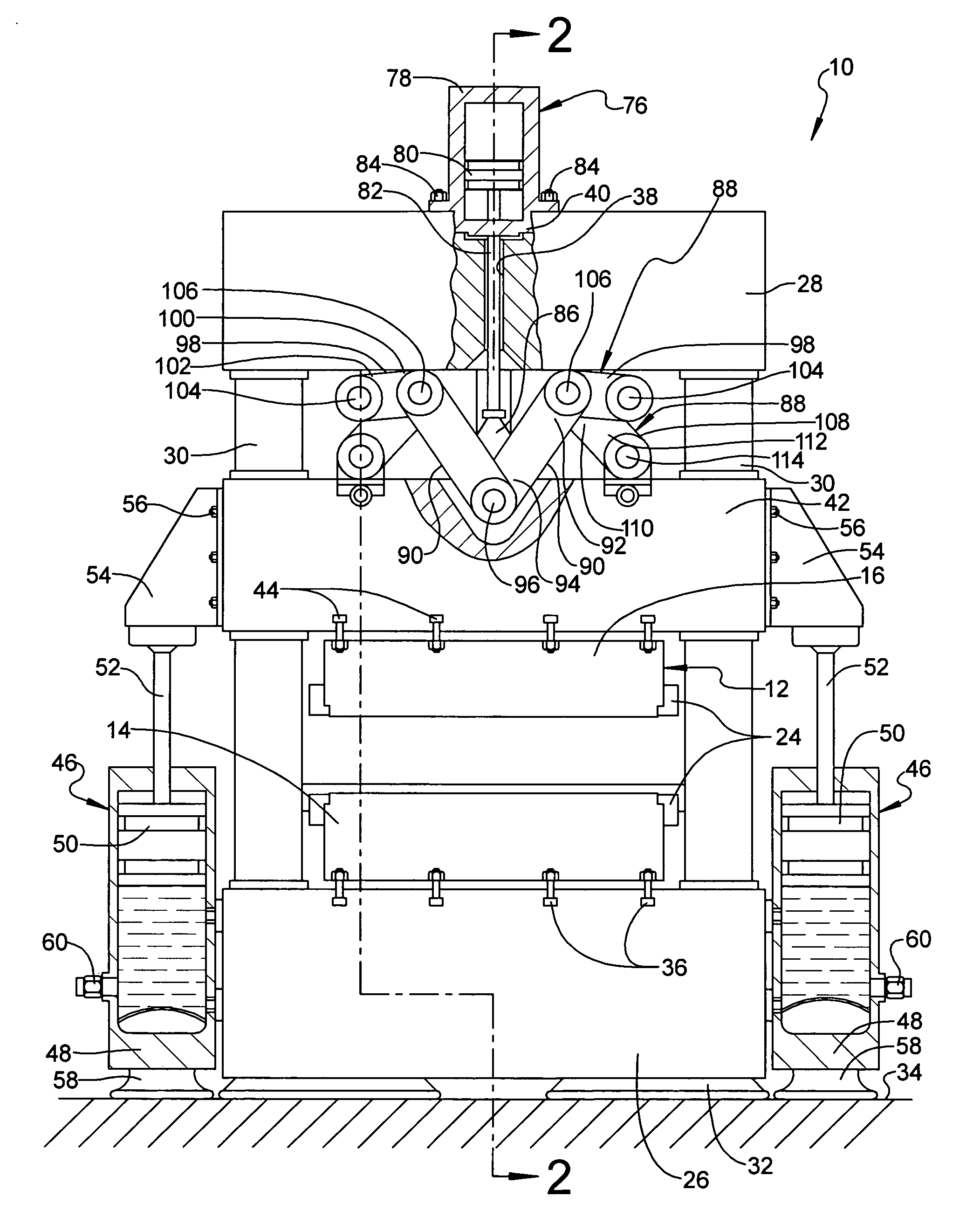
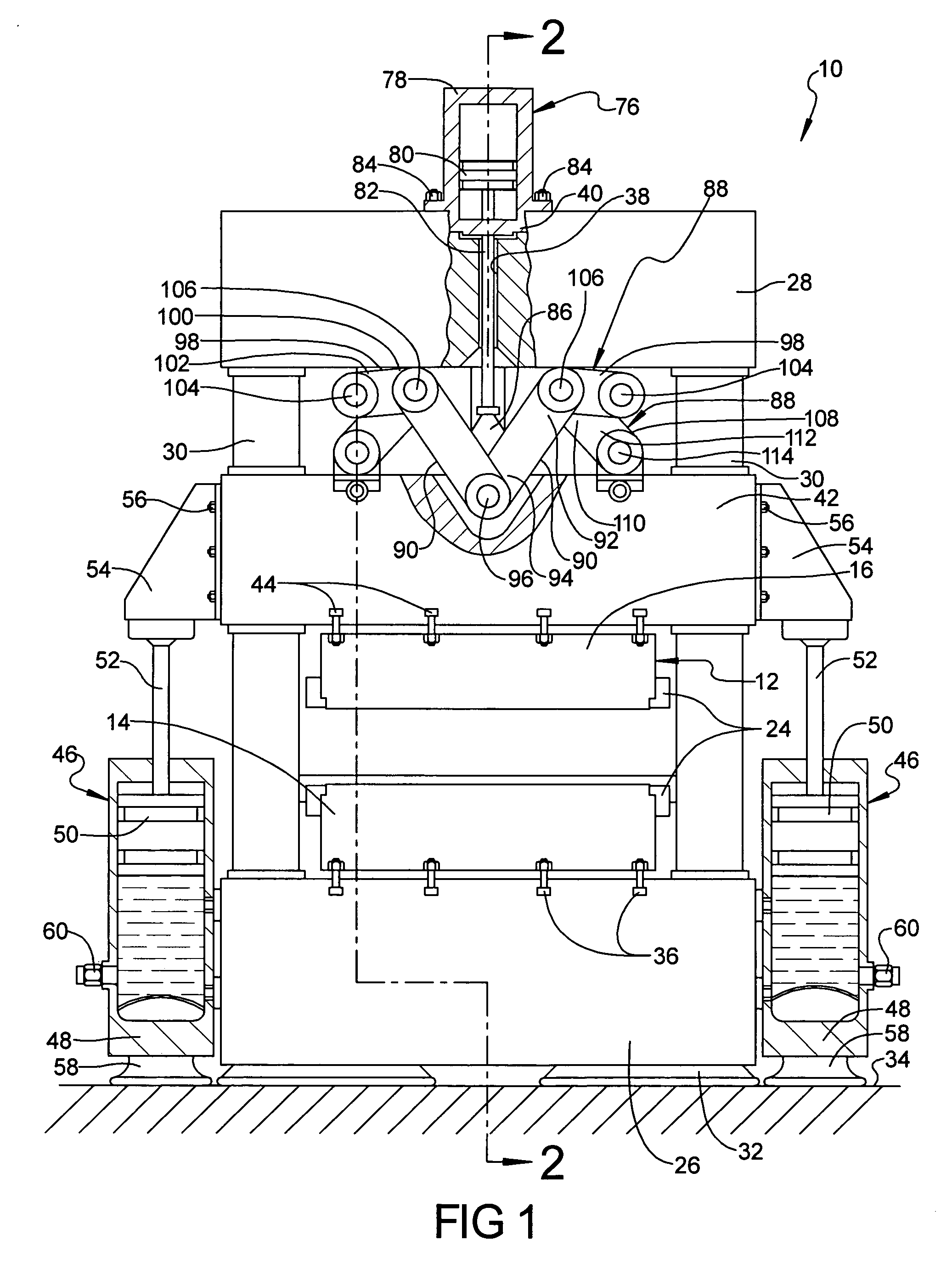
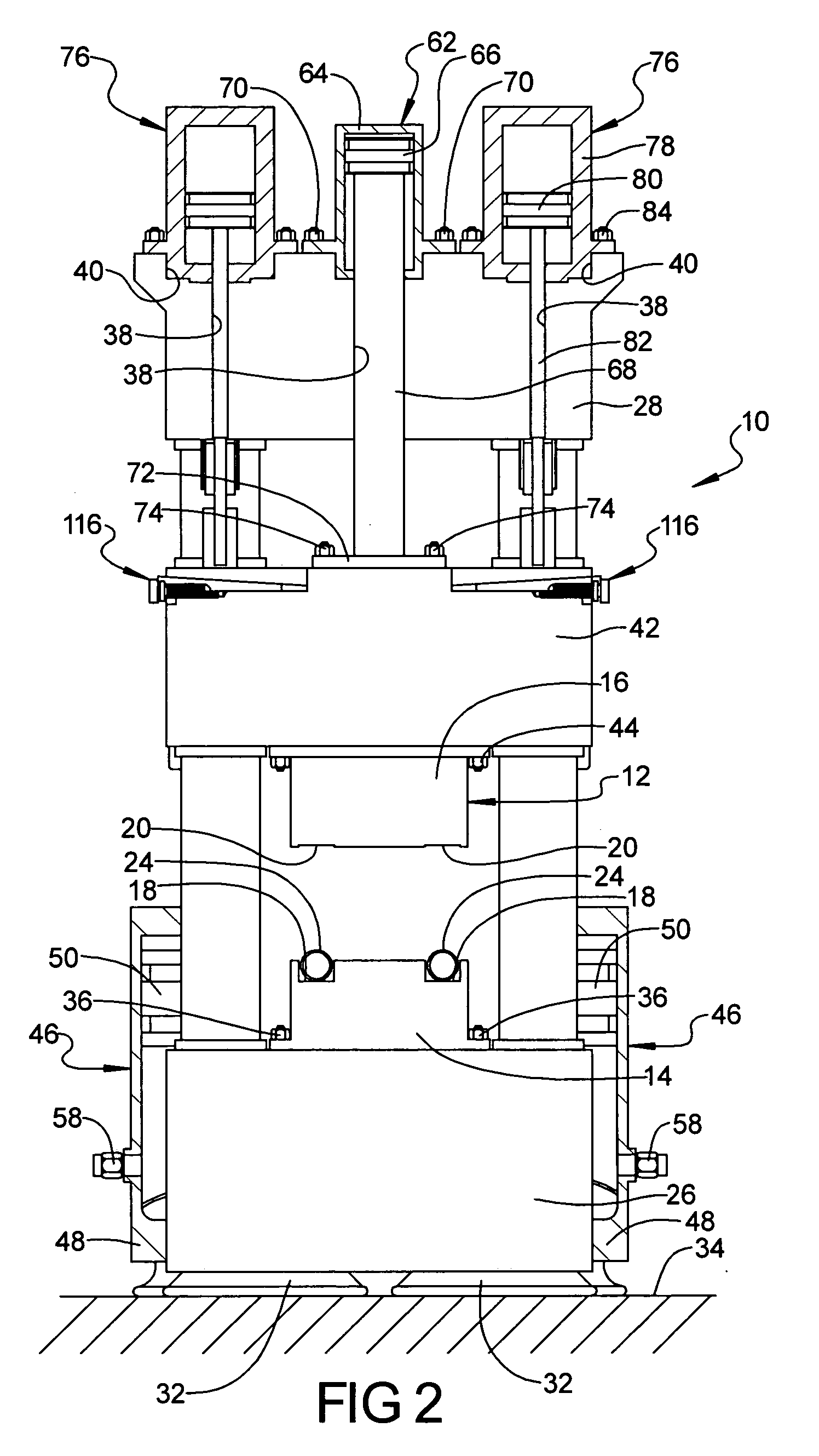
[0023]Referring to the drawings and in particular FIGS. 1 and 2, one embodiment of a clamp assembly 10, according to the present invention, is generally shown for a hydroforming die, generally indicated at 12. The hydroforming die 12 is a die set comprised of a lower die half 14 and an upper die half 16. The lower die half 14 includes at least one, preferably a plurality of tubular forming cavity portions 18. Likewise, the upper die half 16 includes at least one, preferably a plurality of tubular forming cavity portions 20. In the embodiment illustrated, the hydroforming die 12 has a pair of tubular forming cavity portions 18 and 20. It should be appreciated that a combined cross-sectional circumferential measure of the tubular forming cavity portions 18 and 20 total up to generally equal to or slightly greater than the cross-sectional circumferential measure of a tubular member 24.

[0024]The clamp assembly 10 also includes a lower bed 26, an upper bed or crown 28 spaced vertically f...


PUM

PropertyMeasurementUnit
forceaaaaaaaaaa
pressureaaaaaaaaaa
energyaaaaaaaaaa

Abstract

A clamp assembly for a hydroforming die includes a stationary lower bed to support a lower die half of the hydroforming die, a stationary upper bed spaced above the lower bed, at least one guide post extending between the lower bed and the upper bed, a movable slide disposed between the upper bed and the lower bed and movable along the at least one guide post to support an upper die half of the hydroforming die, a lifting cylinder operatively connected to the movable slide to move the movable slide and upper die half toward and away relative to the lower die half, at least one link mechanism connected to the upper bed and the movable slide to equalize a force on the hydroforming die, and at least one linkage cylinder operatively connected to the at least one link mechanism to activate the at least one link mechanism to prevent the movable slide and upper die half from moving away from the lower die half to keep the hydroforming die closed during a hydroforming process.

Description

TECHNICAL FIELD[0001]The present invention relates generally to hydroforming and, more specifically, to a clamp assembly for a hydroforming die.BACKGROUND OF THE INVENTION[0002]It is known to form a cross-sectional profile of a tubular member by a hydroforming process in which a fluid filled tubular member is placed within a cavity of a die and then the die is closed so that the tubular member is pinched within the die. Fluid pressure is then increased inside the tubular member to expand the tubular member outwardly against the cavity of the die to provide a tubular member having a die formed cross-sectional profile.[0003]During hydroforming of the tubular member, conventional hydraulic presses are used. These presses are large, expensive tools used in the hydroforming process mainly as clamping fixtures to keep a die closed against the hydroform fluid pressure. Conventional hydraulic presses require tremendous energy to keep the die halves of the die closed during the hydroforming ...

Claims


Application Information

Patent Timeline
Patent Type & Authority Patents(United States)
IPC IPC(8): B21D26/02B21D9/15
CPCB21D26/039Y10T29/49805
Inventor GHIRAN, MIKE M.SHAH, SANJAY M.JENSEN, DAVID R.KENT, TERRY A.LARSEN, PAUL D.
Owner GM GLOBAL TECH OPERATIONS LLC
Why Eureka
Try Eureka