Disengaging systems

a technology of disengaging systems and levers, applied in mechanical actuators, toy aircrafts, couplings, etc., can solve the problem that the lever system is unable—at least substantially—to apply any for

Active Publication Date: 2006-10-24
SCHAEFFLER TECH AG & CO KG
View PDF16 Cites 20 Cited by
  • Summary
  • Abstract
  • Description
  • Claims
  • Application Information

AI Technical Summary

Benefits of technology

[0009]The present invention provides a lever system for actuating clutches (2a, 2b) or transmission brakes, in particular for motor vehicles, having a lever (7a, 7b, 10) having a first and a second side (i.e., end portion) and at least one support point (B), which at the same time is able to be a fulcrum (8, 8a, 8b), wherein by shifting the support point (B), or the fulcrum (8, 8a, 8b) the actuating force for the clutch (2, 2a, 2b) or the transmission brake is changeable. Thus the lever arms do not have unchangeable lever lengths. This is implemented in a form such that an action of force is realized on a first side of the lever arm by using an energy storage mechanism—designed for example as a disk spring. Thus the first side of the lever arm is determined by the particular position of the fulcrum. The second side of the lever arm causes the action of force on the clutch or transmission brake. In a rest position of the lever system according to the present invention, a changeable fulcrum is located at first essentially in the vicinity of the energy storage mechanism. Now if a clutch or brake is to be engaged, this fulcrum is moved toward the lever end portion whose application of force acts on the clutch or transmission brake. Hence because of the principles of the lever, at first the lever system is unable—at least substantially—to apply any force. But if the fulcrum of this lever system is far away from the energy storage mechanism, or to express it in another way, close to the end portion which acts on the clutch or brake, then great force is available to the lever system according to the invention.

Problems solved by technology

Hence because of the principles of the lever, at first the lever system is unable—at least substantially—to apply any force.

Method used


Image

  • Disengaging systems
  • Disengaging systems
  • Disengaging systems

Examples


Embodiment Construction

[0062]Before describing the figures, it should be stated that the reference symbols have the same meaning throughout all of the figures. In addition, circumferential lines have been omitted from many depictions for reasons of clarity. Where they are included, this is self-explanatory from the nature of the depiction.

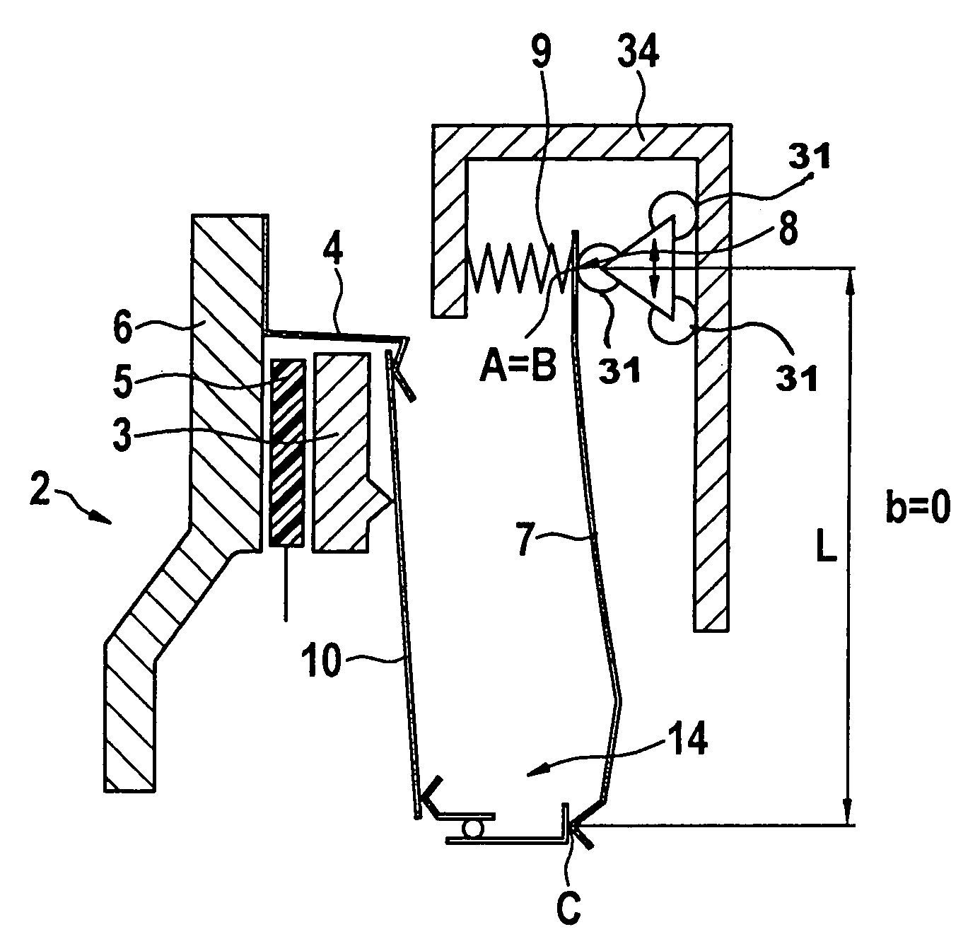
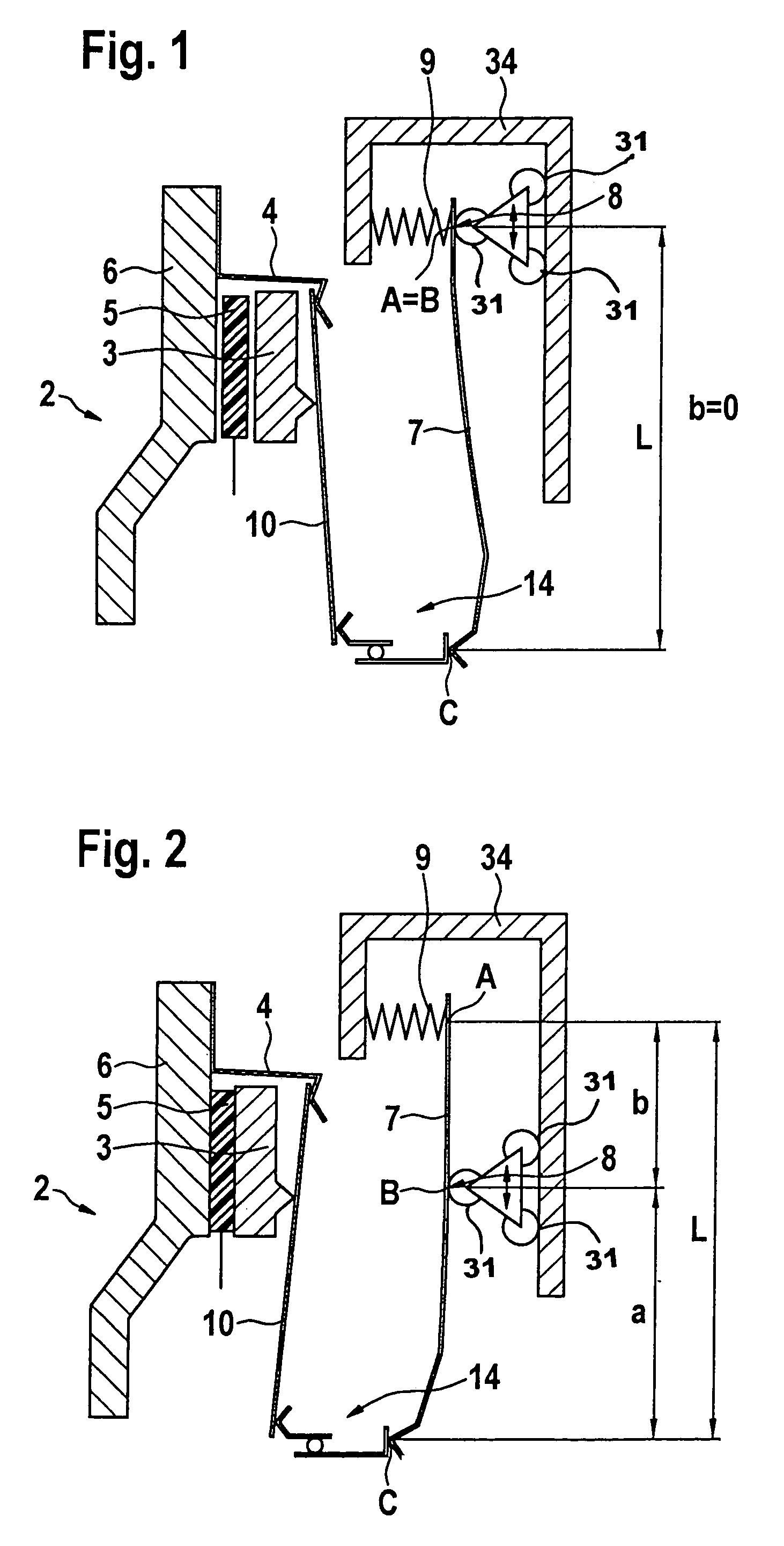
[0063]In FIGS. 1 and 2, only a schematic representation of a clutch with its actuating mechanism according to the present invention may be seen. FIG. 1 shows a disengaged clutch 2, while FIG. 2 shows the same clutch 2 in the engaged state. FIGS. 1 and 2 may therefore be viewed in association. Clutch 2 is made up essentially of a counterpressure plate 6, a clutch disk 5, a pressure plate 3, a clutch cover 4 and a disengaging spring 10, which has the form here of a disk spring. An actuating mechanism for clutch 2 is made up essentially of a lever system which is positioned on a support 34. The actuating mechanism operates through its lever 7 on a thrust bearing 14 (which i...


PUM


Abstract

A lever system for actuating a clutch or a brake for a vehicle, such as a motor vehicle. The actuating force for the clutch or transmission brake is changeable by displacing a fulcrum with respect to a lever. An energy storage mechanism may act at one end portion of the lever and a pressure plate of a clutch or a transmission brake may act, directly or indirectly, on the other end portion.

Description

[0001]Priority is claimed to German Patent Application No. DE 103 09 066.5, filed on Mar. 3, 2003, and to German Patent Application No. DE 103 40 528.3, filed on Sep. 3, 2003. Both of those patent applications are hereby incorporated by reference herein.[0002]The present invention relates to a lever system for actuating clutches or transmission brakes for vehicles—in particular for motor vehicles—where the lever system is modified to actuate the lever.BACKGROUND[0003]According to the known methods, clutches are actuated, for example, in a form in which a lever having unchanging lever lengths is actuated using increasing force. The clutch may also be actuated by a central disengager, however. This central disengager is driven by an electric motor, and the actuation occurs directly through a spur gear system. A disadvantage is that the electric motor must deliver its maximum torque in order to engage the clutch. To do so, it must be fully powered. In order to prevent damage to the clu...

Claims


Application Information

Patent Timeline
Patent Type & Authority Patents(United States)
IPC IPC(8): F16D19/00F16D13/71F16D23/12F16D23/14F16D55/08F16D65/14
CPCF16D23/12F16D65/18F16D65/567F16D2023/126F16D2023/141F16D2065/386F16D2065/784F16D2121/24F16D2125/645F16D2300/14A63H27/10A63H2027/1058A63H2027/1066A63H2027/1075
Inventor FRIEDMANN, OSWALDREIK, WOLFGANGBURKHART, DIRKHAAS, WOLFGANGSCHEUFLER, CHRISTIANMAN, LASZLORABER, CHRISTOPHREIMNITZ, DIRKSCHAEFER, MARKUS
Owner SCHAEFFLER TECH AG & CO KG
Why Eureka
Try Eureka