
Method for calculating refractive correction amount in corneal refractive surgery

a corneal refractive surgery and refractive amount technology, applied in the field of corneal refractive surgery, can solve the problems of affecting the patient's eye, affecting the patient's vision, and the amount of ablation becomes large, so as to avoid a possible serious involvement, correct accurately and easily, and simplify myopic astigmatism.

Inactive Publication Date: 2006-10-24
NIDEK CO LTD
View PDF7 Cites 0 Cited by
  • Summary
  • Abstract
  • Description
  • Claims
  • Application Information

AI Technical Summary

Benefits of technology

[0010]The present invention has been made in view of the above circumstances and has an object to overcome the above problems and to provide an apparatus for use in operating on a cornea, which can correct astigmatism, such as simple myopic astigmatism and mixed astigmatism, accurately and easily by ablating the whole of an optical zone.
[0015]According to the present invention, simple myopic astigmatism and mixed astigmatism can be corrected accurately and easily by utilizing an optical zone at which a patient's eye is not influenced. In addition, in the case of combining an ablation in a strong principal meridian direction with an ablation in a weak principal meridian direction, the apparatus is configured so as to calculate data utilized for converting an astigmatism sign and a rotation of a cylindrical axis, therefore, accurate laser irradiation can be performed with avoiding a possible serious involvement induced by disorder of a cylindrical axis.

Problems solved by technology

Accordingly, in case of the method of correcting myopic astigmatism by ablating the whole in a strong principal meridian direction, an ablation of the periphery tends to be slight as a whole, thus resulting in such a problem that a spherical component is shifted to a hyperopic direction.
However, because of a small optical zone, there is such a problem that a patient's eye is influenced by an optical disorder such a as glare or a halo.
By combining simply, there are such problems that an ablation amount becomes much and a satisfactory result is not obtained.

Method used

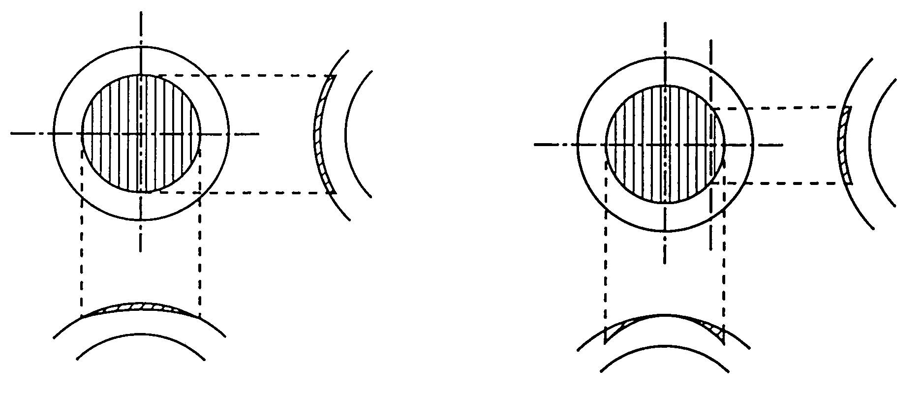

Image

  • Method for calculating refractive correction amount in corneal refractive surgery
  • Method for calculating refractive correction amount in corneal refractive surgery
  • Method for calculating refractive correction amount in corneal refractive surgery

Examples


Embodiment Construction

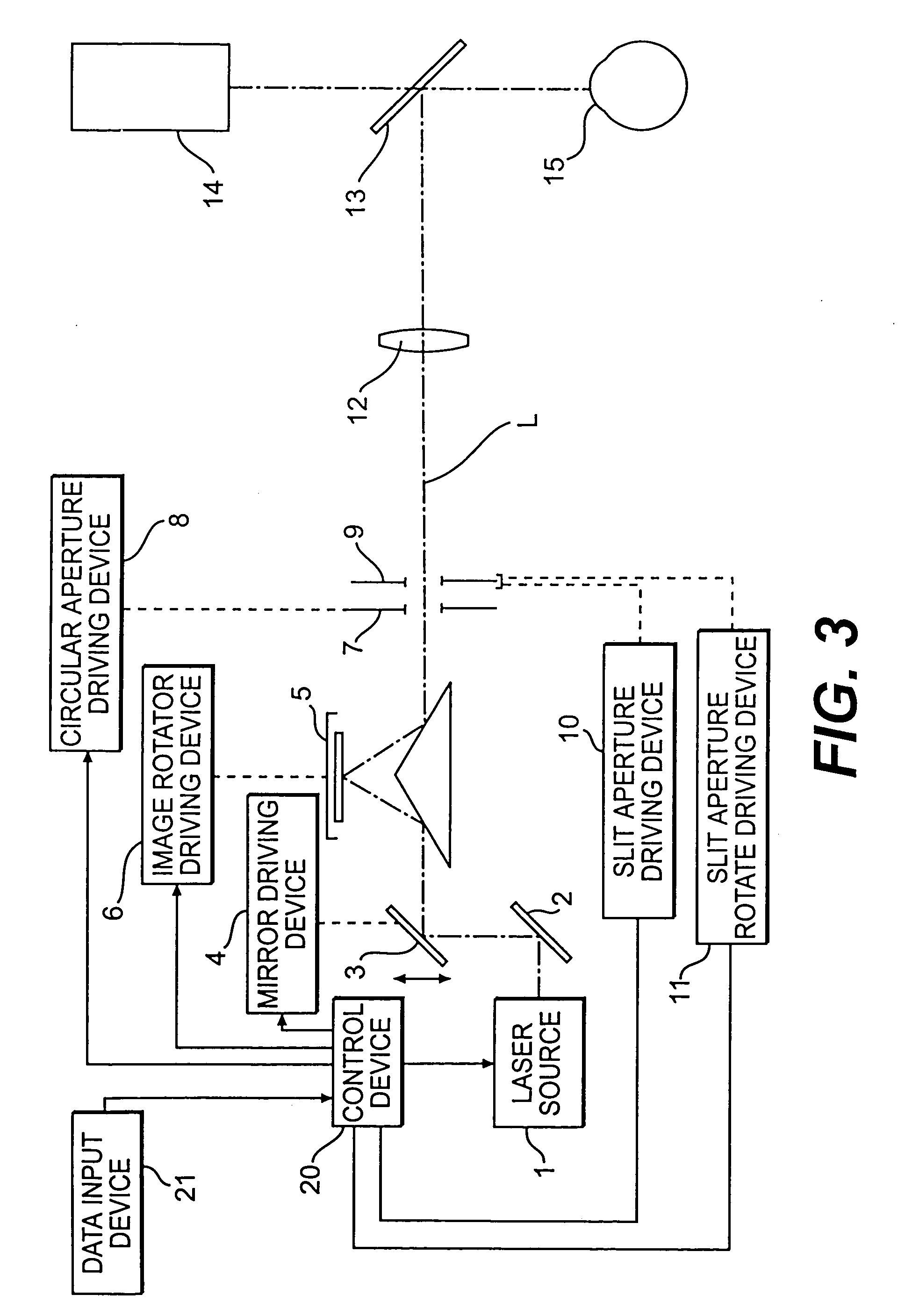
[0020]A detailed description of one preferred embodiment of an apparatus for operation on a cornea embodying the present invention will now be given referring to the accompanying drawings. Firstly, a method of correcting myopic astigmatism and mixed astigmatism according to the present invention will be described below.

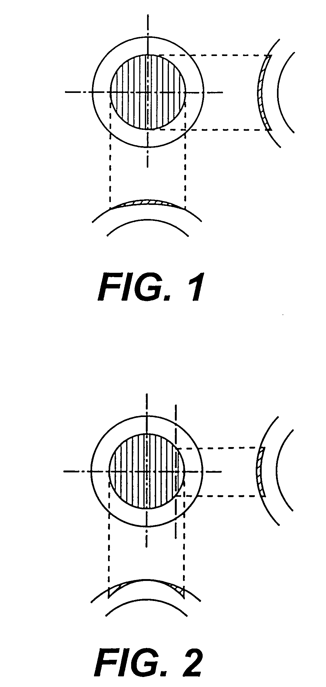
[0021]As shown in FIG. 1, correction for simple myopic astigmatism is performed by ablating a cornea to be a shape similar to a convex cylindrical lens such that a central part is deeply ablated and a periphery is slightly ablated in a certain direction (in a strong principal meridian direction) of a whole optical zone. However, as described above, a central part of a cornea differs from that of a periphery of cornea in an energy density of a laser irradiation. Because of the difference, a spherical component is shifted, thereby correction for simple myopic astigmatism can not performed. Referring to clinical results made by the present inventors, a ratio of a hyperop...


PUM


Abstract

An apparatus for operation on a cornea by ablating with a laser beam for correcting ametropia; the apparatus comprising an input device utilized for inputting each data necessary for correction, a first correcting device for irradiating a laser beam for correcting myopic astigmatism, a second correcting device for irradiating a laser beam for correcting hyperopic astigmatism, a calculating device for calculating each correction-data based on the each inputted data in case of combining the first and second correcting means, and a control device for ablating the cornea by controlling the first and second correcting means based on results calculated by the calculating device.

Description

[0001]The present invention is a continuation of application Ser. No. 09 / 121,917, filed Jul. 24, 1998, pending.BACKGROUND OF THE INVENTION[0002]1. Field of the Invention[0003]The present invention relates to an apparatus for operation on a cornea, and more particularly to the apparatus which corrects ametropia by ablating a corneal surface with a laser beam, being suitable for correcting simple myopic astigmatism and mixed astigmatism.[0004]2. Description of Related Art[0005]In conventional art, there is known an apparatus for operation on a cornea, which corrects ametropia of an examined eye by ablating a corneal surface with an excimer laser. Several methods have been proposed for laser irradiation for such a kind of the apparatus, to include a one shot irradiation method which covers an irradiation area of a cornea with only one shot, a scanning slit method which puts side by side with superposing a slit (rectangular) shaped laser beam in a width direction, and a scanning spot me...

Claims


Application Information

Patent Timeline
Patent Type & Authority Patents(United States)
IPC IPC(8): A61F9/008A61F9/01
CPCA61F9/008A61F9/00804A61F9/00817A61F2009/00872
Inventor CHAYET, ARTURO S.SUZUKI, YOSHITAKA
Owner NIDEK CO LTD
Learn More