Rapid prototype injection molding

a prototype and injection molding technology, applied in the direction of mechanical vibration separation, electric/magnetic/electromagnetic heating, electrical equipment, etc., can solve the problems of high cost, time and skill required to prepare the mold tool, and the strength of the final production part cannot be replicated in prototypes

Inactive Publication Date: 2006-10-24
STRATSYS INC
View PDF5 Cites 158 Cited by
  • Summary
  • Abstract
  • Description
  • Claims
  • Application Information

AI Technical Summary

Benefits of technology

[0013]Using the present invention, an injection molded prototype part can be made from a digital representation of the part within 24 hours by an engineer in an office environment. The design engineer is empowered to build injection modeled parts from CAD files, similar to how rapid prototyping empowered the design engineer to build prototypes from CAD files.

Problems solved by technology

The time and skill required to prepare the mold tool are both significant.
Typically, this process involves placing an order with an outside vendor and waiting several weeks or months for delivery, at high cost.
The strength of a final production part is not, however, replicated in prototypes created by these rapid prototyping techniques.
Additionally, many materials used in these processes are weak.

Method used


Image

  • Rapid prototype injection molding
  • Rapid prototype injection molding
  • Rapid prototype injection molding

Examples


Embodiment Construction

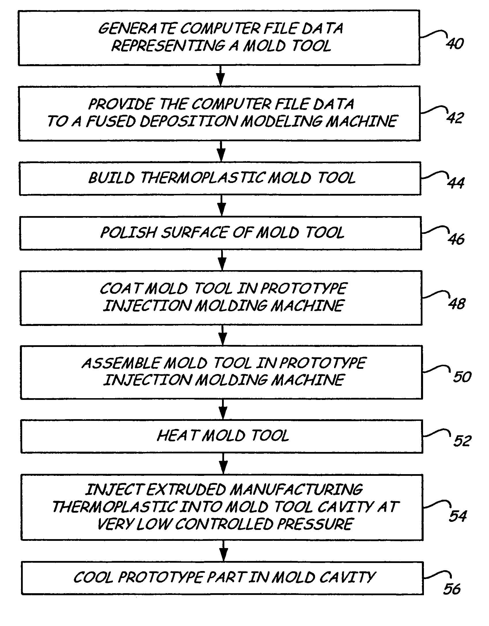
[0018]The method and apparatus of the present invention builds a prototype injection molded part using a non-conductive plastic mold tool, which is preferably built using a rapid prototyping technique. The injection is done by extruding a liquified ribbon of material from an extruder of the type used in a fused deposition modeling machine. Extruded material is injected into a mold cavity of the mold tool at a low speed and low pressure. After the mold cavity is filled, the prototype part thus created is allowed to cool inside of the mold tool. The prototype part is preferably made from a production thermoplastic material which allows an assessment of the strength of a production part. A fused deposition modeling machine may be used for the prototype injection molding apparatus.

[0019]In contrast to manufacturing injection molding processes, the present invention uses low pressures, low flow rates and slow cycle times, allowing the use of a non-reinforced plastic mold tool and providi...


PUM

PropertyMeasurementUnit
pressureaaaaaaaaaa
weight percentaaaaaaaaaa
timeaaaaaaaaaa

Abstract

Disclosed is a method and apparatus for making a prototype injection molded part. An extruder of the type used for fused deposition modeling injects production thermoplastic material into a heated nonconductive plastic mold tool slowly at low pressure in an isothermic process. The mold tool may be built from a CAD drawing by fused deposition modeling or another rapid prototyping technique. Using the present invention, an injection molded prototype part can be made from a digital representation of the part within 24 hours by an engineer in an office environment.

Description

CROSS-REFERENCE TO RELATED APPLICATIONS[0001]This application is a United States national phase entry of PCT International Application No. PCT / US03 / 11854, filed on Apr. 17, 2003, which claims the benefit of U.S. Provisional Application No. 60 / 373,332, filed Apr. 17, 2002.BACKGROUND OF THE INVENTION[0002]The present invention relates to prototyping of injection molded objects, and more particularly to an office-compatible method for rapidly making plastic injection molded prototypes parts.[0003]In a typical injection molding process, plastic is injected at high pressures, extremely quickly, into a thermally conductive metal mold. The molded part is quickly cooled to a temperature at which it can be removed from the mold. The part is then quickly ejected from the mold so that another part can be made, and so that the part does not become stuck on the mold (due to shrink differential). Cooling of large parts continues on a fixture. The goals of production injection modeling are to prod...

Claims


Application Information

Patent Timeline
Patent Type & Authority Patents(United States)
IPC IPC(8): B29C45/00B29C33/40B29C33/38B29C39/02B29C39/24B29C45/77
CPCB29C33/3842B29C45/00B29C71/0009B29C2045/465B33Y80/00B33Y30/00
Inventor CRUMP, STEVEN SCOTTPRIEDEMAN, JR., WILLIAM R.HANSON, JEFFERY J.
Owner STRATSYS INC
Why Eureka
Try Eureka