Rolling bearing unit with rotational speed detecting device

a technology of rotating bearings and detection devices, which is applied in mechanical equipment, instruments, transportation and packaging, etc., can solve the problems of troublesome assembly operation of insufficient sealing performance, and difficulty in miniaturizing the rotational speed detection device section, etc., and achieves the effect of sufficient sealing performan

Active Publication Date: 2006-10-24
NSK LTD
View PDF14 Cites 11 Cited by
  • Summary
  • Abstract
  • Description
  • Claims
  • Application Information

AI Technical Summary

Benefits of technology

[0041]In the case of a rolling bearing unit with a rotational speed detecting device of the present invention constructed as described above, since the rotation-detecting sensor is supported on the metal core, it is possible to achieve miniaturization. Furthermore, it is possible to permit some tolerance in the part of the member with which the edges of the seal member make sliding contact, thus enabling sufficient sealing performance to be ensured.

Problems solved by technology

Therefore, not only is it difficult to miniaturize the rotational speed detecting device section, but also the assembly operation of the rotational speed detecting device section is troublesome.
However, the structure disclosed in Patent Reference 2 requires extremely small sensors and encoders when it is actually used for a rolling bearing unit for an automobile.
Accordingly, it is not capable of practical use with current technical standards.
In the case of such a structure disclosed in Patent Reference 3, the design is not realistic as a combination seal ring.
As a result, in the case where the outer ring and the hub are displaced due to the load applied to the rolling bearing unit during use, the edge of the seal member comes away from the mating surface, so there is a possibility that the necessary sealing performance cannot be ensured.
As a result, it is not possible to make the distance between the surface to be detected and the detecting section small.
Therefore, a structure in which the distance cannot be made small is not desirable.
The reduction in the surface pressure of the contact portion occurs directly at low temperature, and also due to permanent deformation in fatigue of the synthetic resin, which accompanies an excessive increase in surface pressure at high temperature.

Method used


Image

  • Rolling bearing unit with rotational speed detecting device
  • Rolling bearing unit with rotational speed detecting device
  • Rolling bearing unit with rotational speed detecting device

Examples


first embodiment

[First Embodiment]

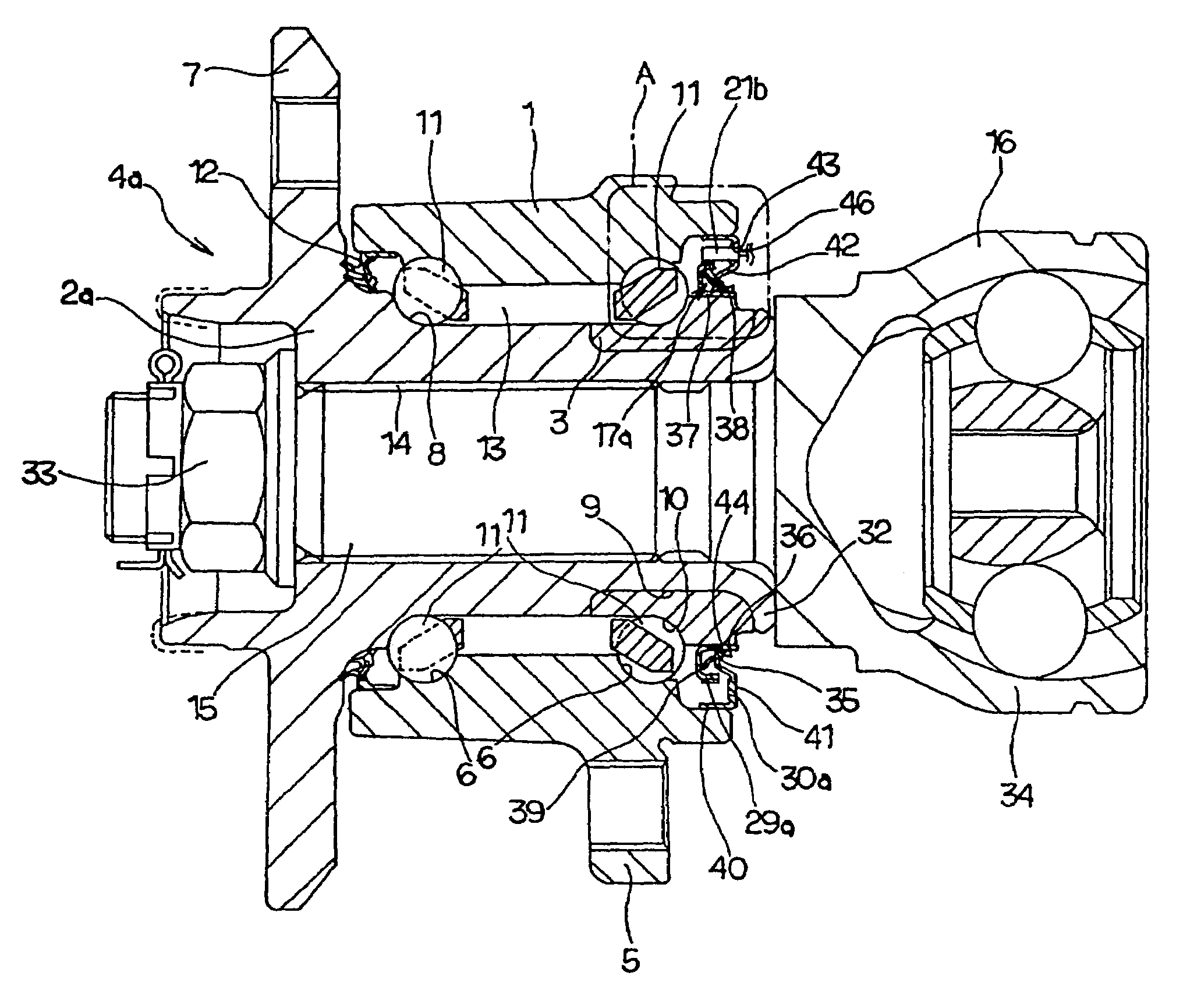
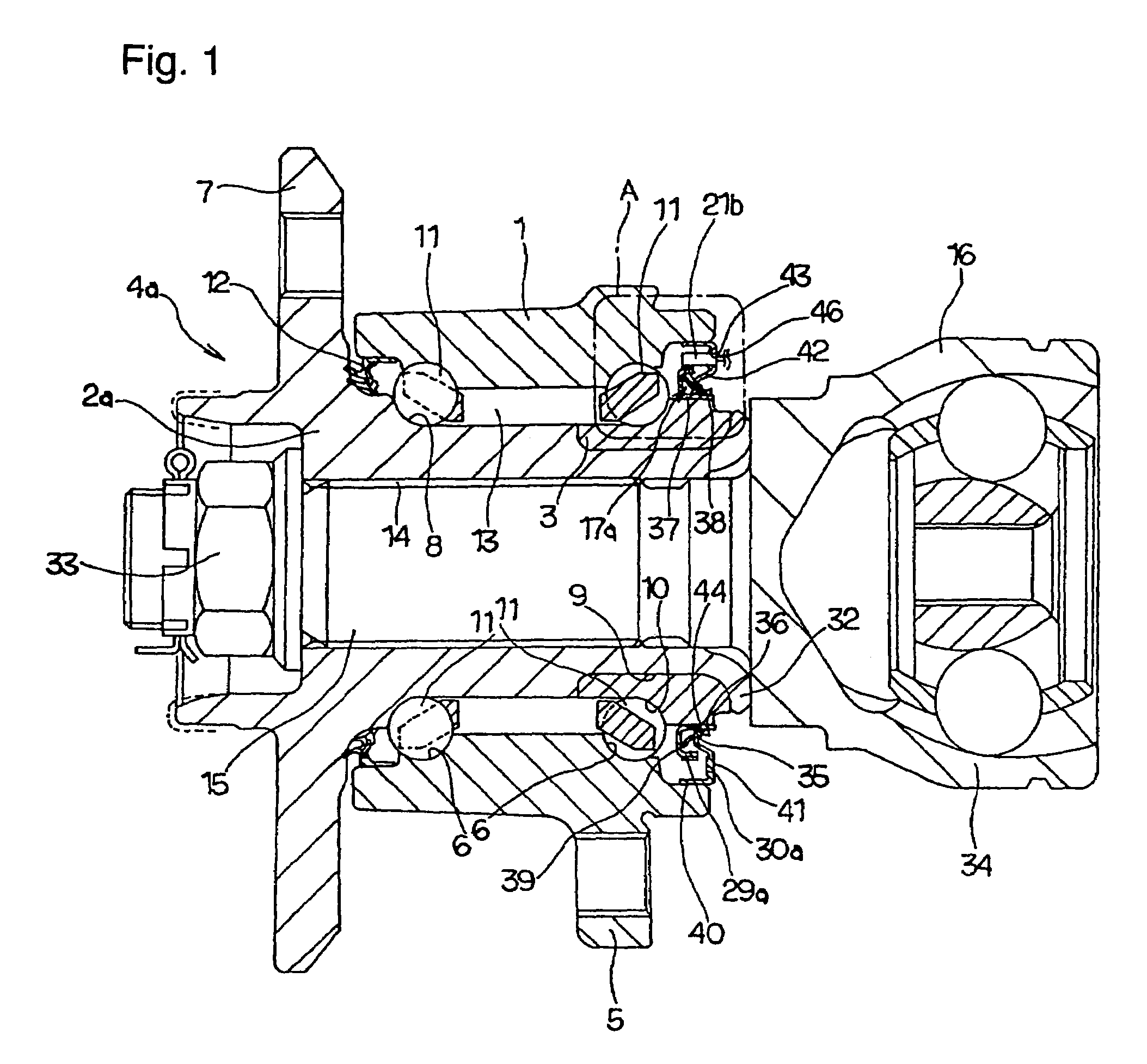
[0051]FIGS. 1 and 2 show a first embodiment according to a first aspect of the present invention. Here, the characteristic of the present invention is that various schemes are devised for the arrangement of an encoder 29a and a rotation-detecting sensor 21b for detecting the rotational speed of a hub 4a, so that miniaturization, maintenance of sealing performance, and maintenance of reliability are all achieved. Since the construction and operation of the other parts are similar to those in the conventional structure as shown in FIGS. 5 and 6, the descriptions associated with similar parts are omitted, or simplified. Hereunder is a description concentrating on the characteristic parts of the present invention and the parts that are different from the conventional structure.

[0052]In the case of the present example, by means of a crimped portion 32 formed by plastic deformation of the inside end of a hub body 2a outwards in the radial direction, pressure is applied t...

second embodiment

[Second Embodiment]

[0060]FIG. 3 shows a second embodiment according to a second aspect of the present invention. In the present example, similarly to the first embodiment described above, a combination seal ring 17a comprises a supporting ring 36, a metal core 30a, and a seal member 44. The supporting ring 36 corresponds to an inner diameter side seal ring element, and the combination of the metal core 30a and the seal member 44 corresponds to an outer diameter side seal ring element. An encoder 29a made of a permanent magnet is supported all around the circumference of the outer peripheral surface of an outer diameter-side cylindrical portion 38 constituting the supporting ring 36.

[0061]Especially in the present example, a rotation-detecting sensor 21c is formed by encapsulating and supporting an IC package 47 and a capacitor 48 mutually connected by a conducting wire, in a holder 49 made of a synthetic resin. The IC package 47 incorporates a magnetic detecting element such as a Ha...

third embodiment

[Third Embodiment]

[0065]FIG. 4 shows a third embodiment according to the first aspect of the present invention. In the first embodiment described previously, the present invention is used for a so-called third generation rolling bearing unit (hub unit) wherein the first inner ring raceway 8 is formed directly on the outer peripheral surface of the middle portion of the hub body 2a (refer to FIG. 1). On the other hand, in the present example, the present invention is used for a so-called second generation rolling bearing unit wherein a first inner ring raceway 8 is formed on the outer peripheral surface of an inner ring 52 separate from a hub body 2b. When the rolling bearing unit is assembled, the inner ring 52 and the inner ring 3 are externally secured to the hub body 2b. The construction and operation of the other parts are similar to those in the first embodiment.


PUM


Abstract

An inner diameter-side cylindrical member 37 of a supporting ring 36 is externally fitted on a shoulder 35 of an inner ring 3 constituting a hub. An encoder 29a is supported on the outer peripheral surface of an outer diameter-side cylindrical portion 38 constituting the supporting ring 36. Further, to a metal core 30a internally fitted to an outer ring 1 is supported and fixed a rotation-detecting sensor 21b, and also a proximal end portion of a seal member 44 is connected and fixed thereto. An edge of at least one of seal lips 45a, 45b, 45c of the seal member 44 is brought to be in sliding contact with the supporting ring 36 around the entire circumference. Since the rotation-detecting sensor 21b and the seal member 44 are supported by the core metal 30a, a rolling bearing unit can be downsized. Further, since the encoder 29a is placed on the outer peripheral surface of the outer diameter-side cylindrical portion 38, the width dimension of a surface with which the edge of each of the seal lips 45a, 45b, 45c is brought to be in sliding contact is secured for excellent sealing ability. The structure provides a rolling bearing unit with a rotating speed-detecting device, where the bearing unit is downsized and has a construction capable of achieving excellent sealing ability.

Description

CROSS REFERENCE TO RELATED APPLICATION[0001]This application is a continuation-in-part of PCT application number PCT / JP2004 / 010309 filed on Jul. 20, 2004, now International Publication WO 2005 / 010382 and claims priority from Japanese Patent Application 2003-279365 filed on Jul. 24, 2003, the contents of which are herein incorporated by reference.TECHNICAL FIELD[0002]The present invention relates to improvements to a rolling bearing unit with a rotational speed detecting device, which is used for rotatably supporting the wheel of an automobile with respect to a suspension system, and for detecting the rotational speed of the wheel.BACKGROUND ART[0003]A rolling bearing unit is used to rotatably support the wheel of an automobile with respect to a suspension system. Moreover, in order to control an anti-lock brake system (ABS) or a traction control system (TCS), it is necessary to detect the rotational speed of the wheel. Therefore, a method has been widely used recently where the whee...

Claims


Application Information

Patent Timeline
Patent Type & Authority Patents(United States)
IPC IPC(8): G01B7/30F16C19/00F16C19/18F16C19/52F16C33/58F16C33/78F16C41/00G01P3/44G01P3/487
CPCF16C41/007F16J15/326G01P3/443G01P3/487F16C33/7879F16C19/186F16C2326/02F16C19/185F16C19/02F16C19/08F16C19/52F16C33/76
Inventor SAKAMOTO, JUNSHI
Owner NSK LTD
Why Eureka
Try Eureka