

Cleaning device for collecting toner on a surface of an image forming apparatus
a technology of cleaning device and image forming apparatus, which is applied in the direction of electrographic process apparatus, instruments, optics, etc., can solve the problems of increasing the size of the cleaning device and cost, and reducing so as to achieve the effect of prolonging the service life of the intermediate transfer member
- Summary
- Abstract
- Description
- Claims
- Application Information
AI Technical Summary
Benefits of technology
Problems solved by technology
Method used
Image

Examples
first embodiment
(First Embodiment)
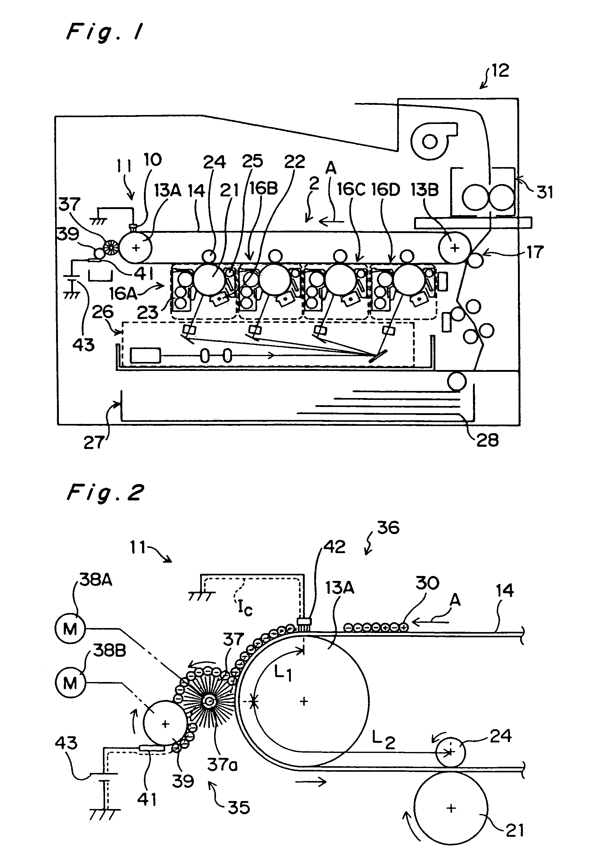
[0072]FIG. 1 shows a laser printer 12 of tandem process method exemplifying an image forming apparatus having a secondary cleaning device 11 (hereinbelow referred to as a cleaning device 11) according to a first embodiment-of the present invention. It is to be noted that in the present embodiment, a normal charge polarity of toner is negative.
[0073]An intermediate transfer belt 14 (hereinbelow referred to as a transfer belt 14) stretched between a pair of stretching rollers 13A and 13B is forwarded to a direction shown with an arrow A by rotation of the stretching rollers 13A, 13B. Around the transfer belt 14, there are disposed first to fourth image forming units 16A–16D, a secondary transfer device 17, and a cleaning device 11.
[0074]The image forming units 16A–16D each transfer images in yellow (Y), magenta (M), cyan (C) and black (Br) to the transfer belt 14. The image forming units 16A–16D have the same structure, in which a charging device 22, a developing dev...
second embodiment
(Second Embodiment)
[0089]In a second embodiment of the present invention shown in FIG. 6, instead of the fur brush 37 (see FIG. 2), the collection section 35 is provided with a conductive elastic roller 45 having a conductive rubber layer on the perimeter of a core metal. Other structure and operation of the second embodiment are similar to those of the first embodiment.
third embodiment
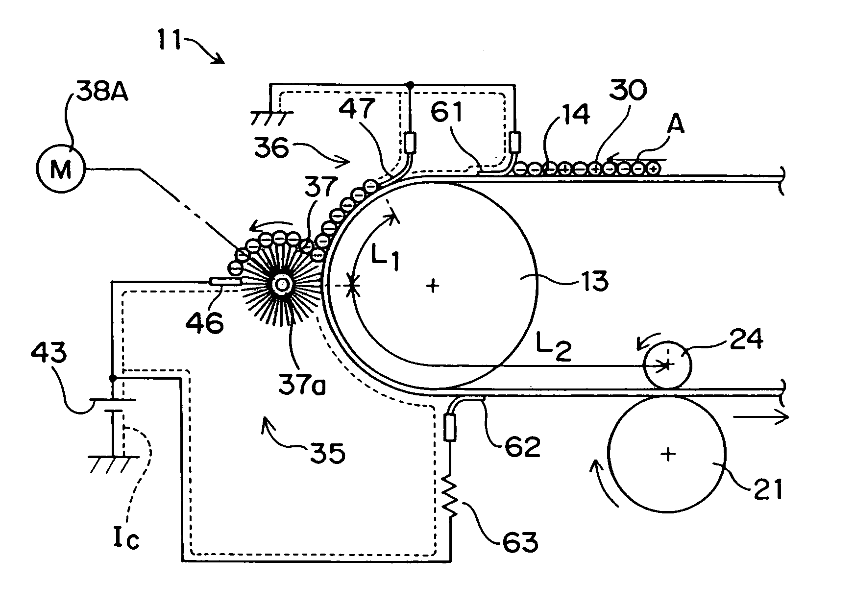
(Third Embodiment)
[0090]In a third embodiment of the present invention shown in FIG. 7, the fur brush 37 of the collection section 35 has conductivity and is connected to the constant-current d.c. power supply 43 via a flicker46 that functions also as a contact member. The toner 30 collected by the fur brush 37 is scraped off by the flicker 46. Moreover, instead of the conductive brush 42 (see FIG. 2), the discharging section 36 is provided with a conductive film 47. The distal end side of the conductive film 47 is in contact with the transfer belt 14, while its proximal end side is supported by a holder having conductivity. The conductive film 47 is grounded via the holder. Cleaning current IC flows from the constant-current d.c. power supply 43 through the flicker 46, the fur brush 37, and the transfer belt 14 to the conductive film 47. Other structure and operation of the third embodiment are similar to those of the first embodiment.
PUM
 Abstract
Description
Claims
Application Information