Network element terminal data interface system and method

Inactive Publication Date: 2006-10-24
RPX CORP +1
View PDF19 Cites 11 Cited by
  • Summary
  • Abstract
  • Description
  • Claims
  • Application Information

AI Technical Summary

Benefits of technology

[0020]As illustrated in FIG. 3 (0300), the present invention as embodied in a system comprises a software driven (0301) user interface (0302) that an operator (0303) uses to control a variety of network elements (0304, 0305) via a communications network (0306) under the direction of a TL1 composer/parser (0307). The TL1 composer/parser (0307) processes commands from the user interface (0302).
[0021]While there is a part of TL1DAT composer/parser (0307) that takes a full TL1 command and populates all the parameter fields with the appropriate data (a “parser”) and another part of the application that takes all the data in the parameter fields to create a full TL1 command (a “composer”), neither of these parts are utilized when sending TL1 commands from a batch/log file (0308). Commands from a batch file (0308) are sent as is by a batch processor (0309) to the network elements (0304, 0305) without any checking or parsing. While batch commands are sent to network elements (0304, 0305) without additional processing in the described preferred embodiment, one skilled in the art will recognize that there may be advantages to having the batch processor (0309) communicate directly with the TL1 composer/parser (0307) to communicate batch commands over the communication network interface (0306) to the network elements (0304, 0305). In this context the TL1 composer/parse

Problems solved by technology

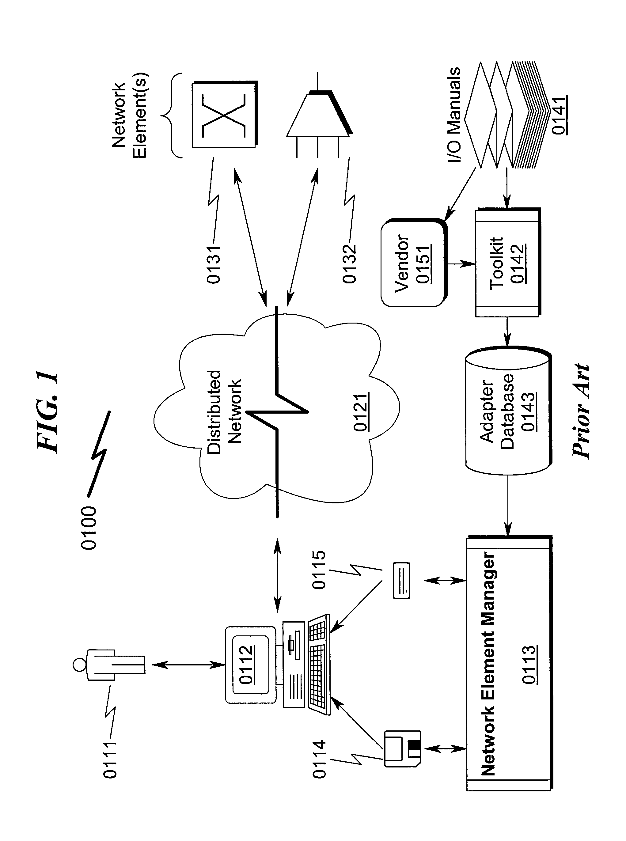
When new network elements (0131, 0132) are to be added or software updated in this configuration, it is particularly difficult for the customer (0111) to upgrade the adapter.
The difficulty in this architecture (0100) is in the logistical problems associated wi

Method used


Image

  • Network element terminal data interface system and method
  • Network element terminal data interface system and method
  • Network element terminal data interface system and method

Examples


Embodiment Construction

[0052]While this invention is susceptible of embodiment in many different forms, there is shown in the drawings, and will herein be described in detail, various preferred embodiments of the invention with the understanding that the present disclosure is to be considered as an exemplification of the principles of the invention and is not intended to limit the broad aspect of the invention to the embodiment illustrated.

[0053]The numerous innovative teachings of the present application will be described with particular reference to the presently preferred embodiment, wherein these innovative teachings are advantageously applied to the particular problems of a NETWORK ELEMENT TERMINAL DATA INTERFACE SYSTEM AND METHOD. However, it should be understood that this embodiment is only one example of the many advantageous uses of the innovative teachings herein. In general, statements made in the specification of the present application do not necessarily limit any of the various claimed inven...


PUM


Abstract

A NETWORK ELEMENT TERMINAL DATA INTERFACE (NETDI) system and method incorporating a terminal user interface which permits manipulation of network elements using a hardware-specific control language is disclosed. The present invention teaches automatic generation of on-line help directly from I/O manual specifications and translation of operator commands into network element specific protocols via the use of a network element database and associated XML repository. Various preferred embodiments of the present invention incorporate the use of TL1 composer/parsers to permit the automatic generation of Translation Language 1 interfaces between an operator console and a wide variety of telecommunication network elements. The present invention operates over a wide variety of communication media and permits a significant reduction of software maintenance with respect to on-line help generation directly from I/O manual specifications as well as automated incorporation of new network element features into existing operator console environmental controls, resulting in a drastic reduction in the required network element control language proficiency of network operators in any given telecommunications environment.

Description

CROSS REFERENCE TO RELATED APPLICATIONS[0001]Not ApplicablePARTIAL WAIVER OF COPYRIGHT[0002]All of the material in this patent application is subject to copyright protection under the copyright laws of the United States and of other countries. As of the first effective filing date of the present application, this material is protected as unpublished material.[0003]However, permission to copy this material is hereby granted to the extent that the copyright owner has no objection to the facsimile reproduction by anyone of the patent documentation or patent disclosure, as it appears in the United States Patent and Trademark Office patent file or records, but otherwise reserves all copyright rights whatsoever.STATEMENT REGARDING FEDERALLY SPONSORED RESEARCH OR DEVELOPMENT[0004]Not ApplicableREFERENCE TO A MICROFICHE APPENDIX[0005]Not ApplicableFIELD OF THE INVENTION[0006]The present invention is related to the general area of distributed Element Management Systems (EMS) that are utilize...

Claims


Application Information

Patent Timeline
IPC IPC(8): G06F15/16
CPCG06F17/30569H04L41/0253H04L41/0266H04L41/22G06F16/258
Inventor GREENWALT, AMBER D.ELLIS, RANDY J.BENZ, ADAM S.UTTERBACK, ROBERT G.ATKINS, CHRISTOPHER D.MAZNARITZ, DEBORAH L.BROWN, TIMOTHY P.LUO, ZHEJINGMCGLADE, BRYAN J.
Owner RPX CORP
Why Eureka
Try Eureka