Piezoelectric sensor, sensor array, and associated method for measuring pressure

a technology of piezoelectric sensors and sensors, applied in the field of piezoelectric sensors, can solve the problems of limiting the number of pressure monitoring devices that can be disposed on a particular test member, restricting the locations, and devices that are too large for mounting on small surfaces

Inactive Publication Date: 2006-10-31
THE BOEING CO
View PDF9 Cites 64 Cited by
  • Summary
  • Abstract
  • Description
  • Claims
  • Application Information

AI Technical Summary

Problems solved by technology

However, the number of such pressure monitoring devices that can be disposed on a particular test member is limited by the size of the devices.
The size of each device also restricts the locations in which the devices can be provided.
For example, the devices can be too large for mounting on small surfaces, in thin portions, or at sharp edges of the test member.
In addition, the placement of each device requires a hole to be drilled in the test member and addition of a channel to route the wires, thereby further limiting the number of devices that can be disposed on a single test member.
Further, once the holes and channels are formed in the test member and the devices are mounted in the holes, the devices cannot be easily repositioned.
The formation of the holes and channels also typically results in significant modification and structural weakening of the test device.

Method used


Image

  • Piezoelectric sensor, sensor array, and associated method for measuring pressure
  • Piezoelectric sensor, sensor array, and associated method for measuring pressure
  • Piezoelectric sensor, sensor array, and associated method for measuring pressure

Examples


Embodiment Construction

[0019]The present invention now will be described more fully with reference to the accompanying drawings, in which some, but not all embodiments of the invention are shown. This invention may be embodied in many different forms and should not be construed as limited to the embodiments set forth. Like numbers refer to like elements throughout.

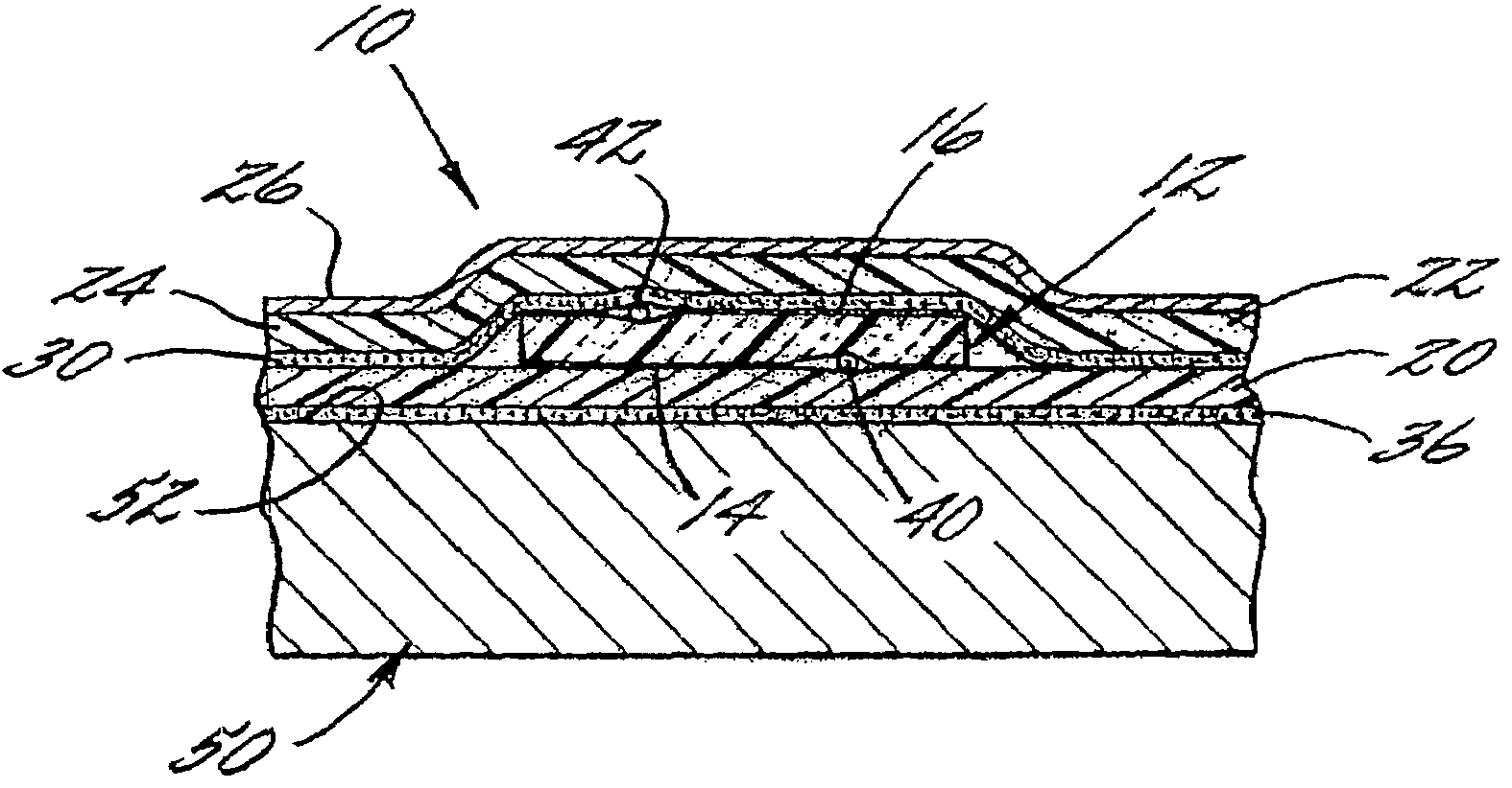
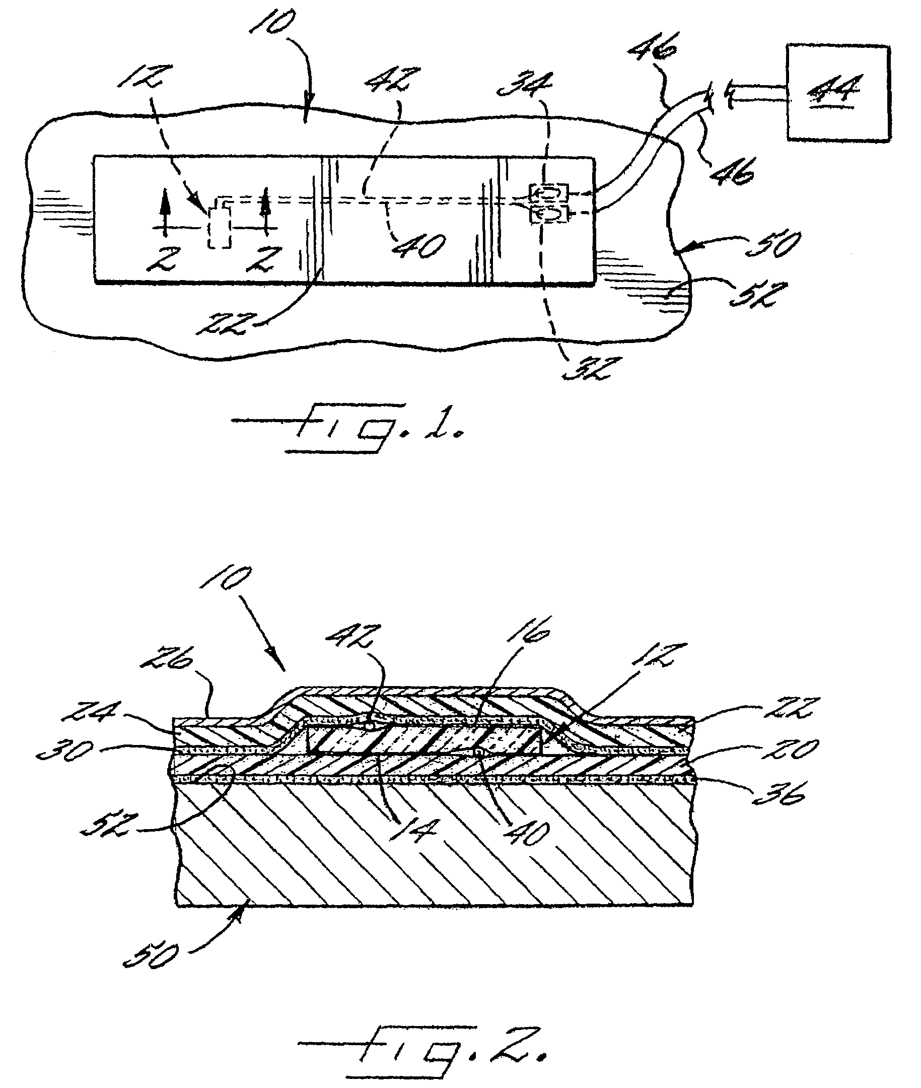
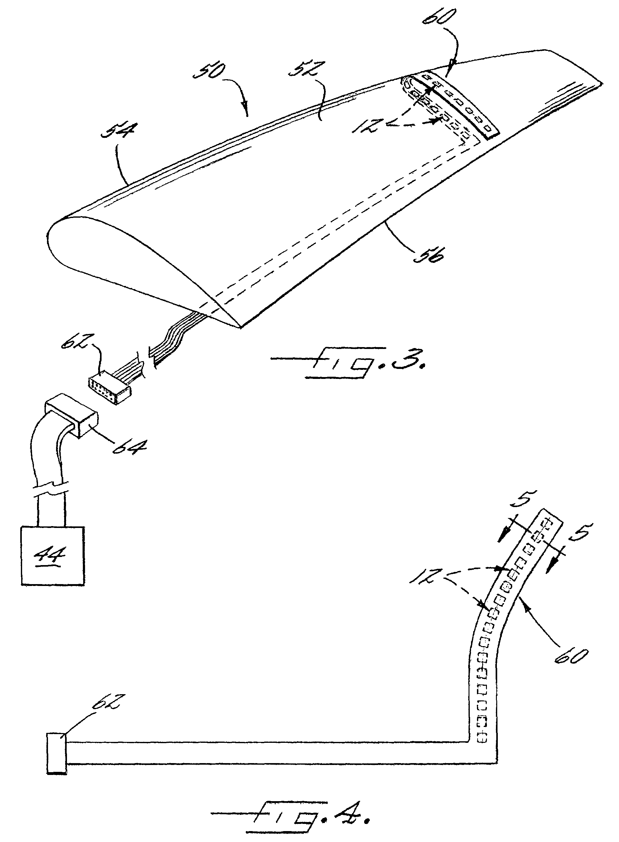
[0020]A sensor 10 for measuring a pressure or force is shown in FIG. 1. The sensor 10 is configured to be disposed on a surface 52 of a test member 50 for measuring the pressure exerted on the test member 50 (FIG. 3). The sensor 10 can be disposed on, and attached to, various test members. Further, by the term “test,” it is meant that the sensor 10 is disposed on the member 50 during normal operation of the member, and the operation can be a typical operation of the member, an experimental operation, or otherwise. For example, the test member 50 can be an airfoil, such as a wing during aerodynamic testing of the wing, and the sensor 10 can be us...


PUM


Abstract

A sensor, sensory array, and associated method for measuring a pressure are provided. The sensor includes a piezoelectric sensory device that is disposed on an electrically insulative substrate that can be adhered to a member for measuring the pressure on the member. The piezoelectric sensory device defines first and second contact surfaces and is adapted to provide an electric potential between the surfaces that corresponds to a pressure on the piezoelectric sensory device. Conductive terminals are in electrical communication with the piezoelectric sensory device and therefore also provide the electric potential indicative of the pressure on the surface of the test member. An electrically insulative sheet is disposed opposite the piezoelectric sensory device from the substrate. An electronic monitoring device can be electrically connected to the piezoelectric sensory device via the terminals and configured to monitor the electric potential provided by the piezoelectric sensory device.

Description

CROSS-REFERENCES TO RELATED APPLICATIONS[0001]This application is a continuation-in-part of U.S. patent application Ser. No. 11 / 059,833, filed on Feb. 17, 2005, now abandoned which is hereby incorporated herein in its entirety by reference.FIELD OF THE INVENTION[0002]The present invention relates to the measurement of pressure and, in particular, relates to a sensor and method for measuring pressure on a surface of a test member such as an airfoil.DESCRIPTION OF RELATED ART[0003]Wind tunnel testing is often used for testing vehicles such as airplane. For example, a portion of an aircraft or a full or partial model of an aircraft can be positioned in a wind tunnel and subjected to a flow of air to determine characteristics of the member. According to one typical testing method, the static and dynamic pressures are measured at a number of positions on the surface of the test member. For example, pressure monitoring devices can be disposed on the wings, vertical or horizontal tail sect...

Claims


Application Information

Patent Timeline
Patent Type & Authority Patents(United States)
IPC IPC(8): G01P15/09
CPCG01L9/008
Inventor TAVARES, MATTHEW R.MORRIS, DONALD G.BASHAM, RICHARD R.GILLMORE, JAMES M.
Owner THE BOEING CO
Why Eureka
Try Eureka