Adjustable tension shade assembly

a tension shade and assembly technology, applied in the field of window shades, can solve the problems of substantially fixed length of prior art assemblies, affecting the sizing of shade members, and affecting so as to facilitate the sizing of the shade members, minimize the lateral force, and be easily adjusted.

Inactive Publication Date: 2006-10-31
KENNEY MFG
View PDF30 Cites 50 Cited by
  • Summary
  • Abstract
  • Description
  • Claims
  • Application Information

AI Technical Summary

Benefits of technology

[0010]The present invention solves the problems associated with the prior art shade assemblies. The adjustable tension shade of the present invention includes a shade roller having a tubular body and a telescoping spring-biased axle. The shade roller has a first portion that slidably resides within a second portion to form the shade roller. The axle has a axle body portion and an adjustment rod portion that is received therein. The axle body portion has an adjustment spring contained therein. The adjustment rod portion has a raised shoulder that cooperates with the adjustment spring contained in the axle body portion to position the adjustment rod therein. The adjustment spring urges the free ends of the axle away from each other. As a result, the axle body member can be retained within a window casement by friction in similar fashion to a standard spring tension curtain rod. The ends of the axle have cushioned footings attached thereon to retain the entire assembly in place without damaging the window casement walls.
[0012]However, the shade assembly of the present invention can be adjusted in width across a wide range to accommodate window casements of different sizes. The shade assembly is fit to a given window and then the shade itself is selected to fit to the adjusted to length. The shade member can be cut to the size and then attached directly onto the second (outer) tubular member so that it can be wound thereabout, as desired. However, it is also possible to provide a window shade member that can be sized by the user without cumbersome cutting. As seen in U.S. Pat. No. 4,438,799, issued to Comeau and commonly owned with the instant invention, a shade of adjustable width, using tear-way strips, can be used in conjunction with the present invention to facilitate the sizing of the shade member. Using the easy-adjusting shade member of Comeau '799, the shade assembly can be provided in a single kit for a consumer to custom install and fit a shade assembly into a wide range of window casement sizes.
[0013]Accordingly, it is an object of the present invention to provide an adjustable tension shade rod that can be easily adjusted to fit a range of window sizes.
[0015]Yet another object of the present invention is the provision for an adjustable tension shade that can be mounted to a window casement without damaging the window casement.
[0016]Yet another object of the present invention is the provision for an adjustable tension shade that minimizes the lateral forces on the roller of the tension shade thereby preventing jamming or dislodgment of the tension shade from the window casement.

Problems solved by technology

This is particularly problematic in connection with the sale of such shades because different sizes of shades must be available for purchase to fit the different sizes of windows.
This device is not intended to fit to a wide range of window sizes.
These prior art assemblies, however, suffer from the disadvantage of being of a substantially fixed length.
Another disadvantage of prior art shade rollers is that the holding force exerted by the ends of the assembly is through the roller itself.
This means that there is increased friction that keeps the roller from turning freely.

Method used


Image

  • Adjustable tension shade assembly
  • Adjustable tension shade assembly
  • Adjustable tension shade assembly

Examples


Embodiment Construction

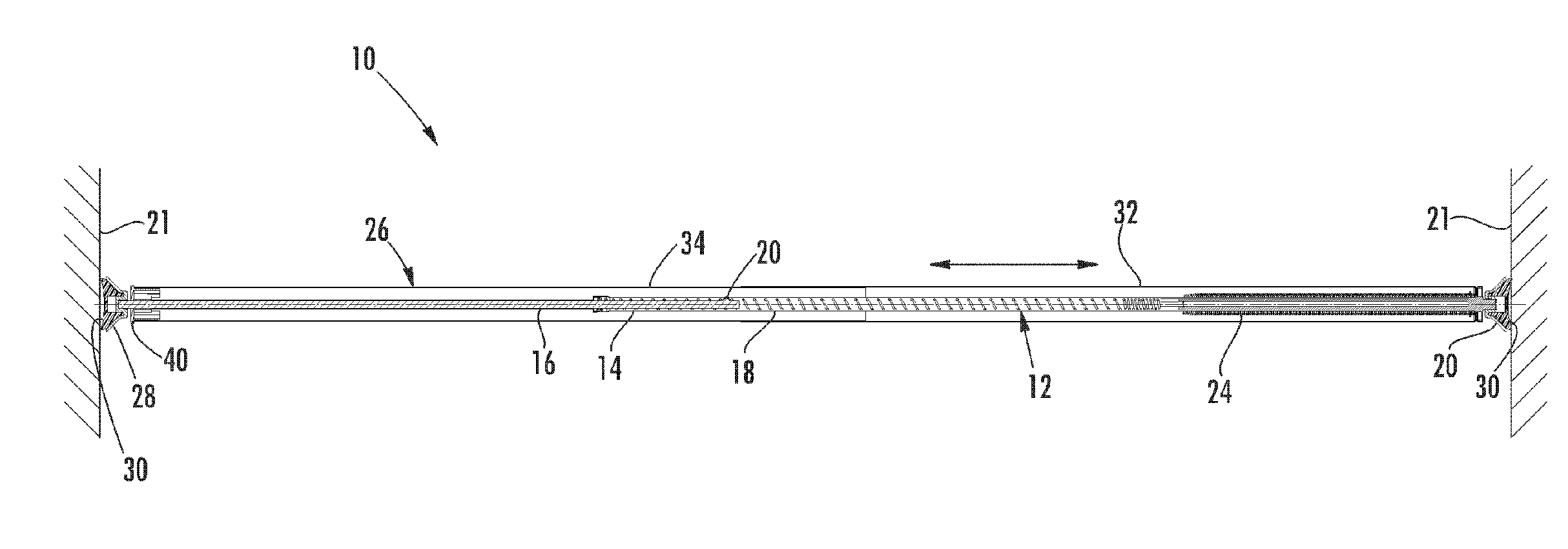
[0025]The adjustable tension shade rod of the present invention is shown generally at 10 in FIGS. 1–7. As will hereinafter be more fully described, the present invention provides an inexpensive adjustable tension shade rod that can be adjusted to fit many windows of varying dimensions without the need for additional mounting hardware and without damaging the window casement walls.

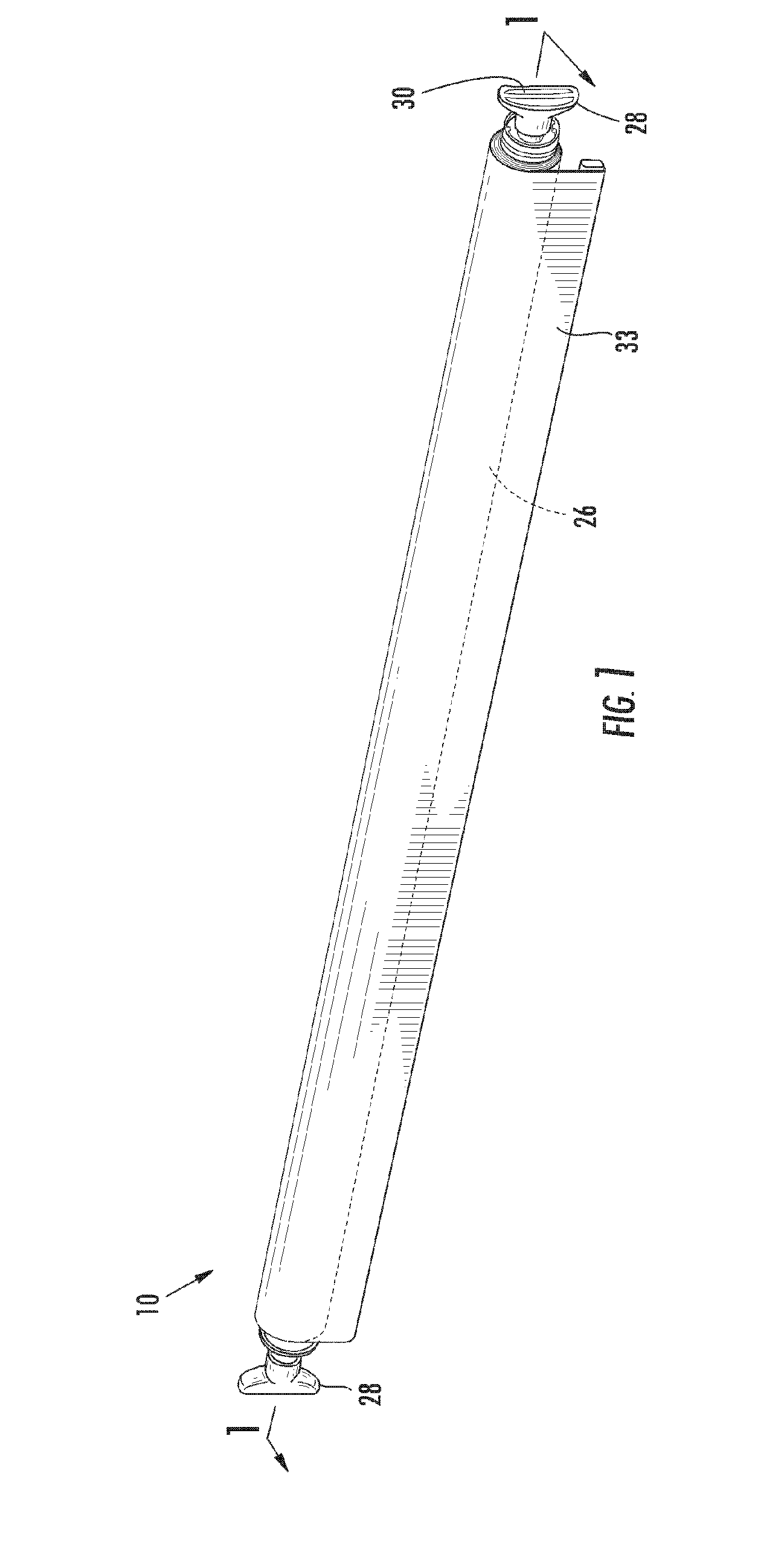
[0026]Referring first to FIG. 1, a front perspective view of the spring tension rod assembly 10 of the present invention is shown to include a telescoping shade roller 26 with a foot 28 on each opposing sides thereof. As will be described in detail below, the shade roller 26 is rotatably mounted relative to each foot 28. A grip surface 30 is provided on the ends of each foot 28 is a grip surface for communicating with a mount surface, such as a window casement. A shade 33 is wound about the shade roller 26. FIG. 1 illustrate the shade 33 fully would about the shade roller 26.

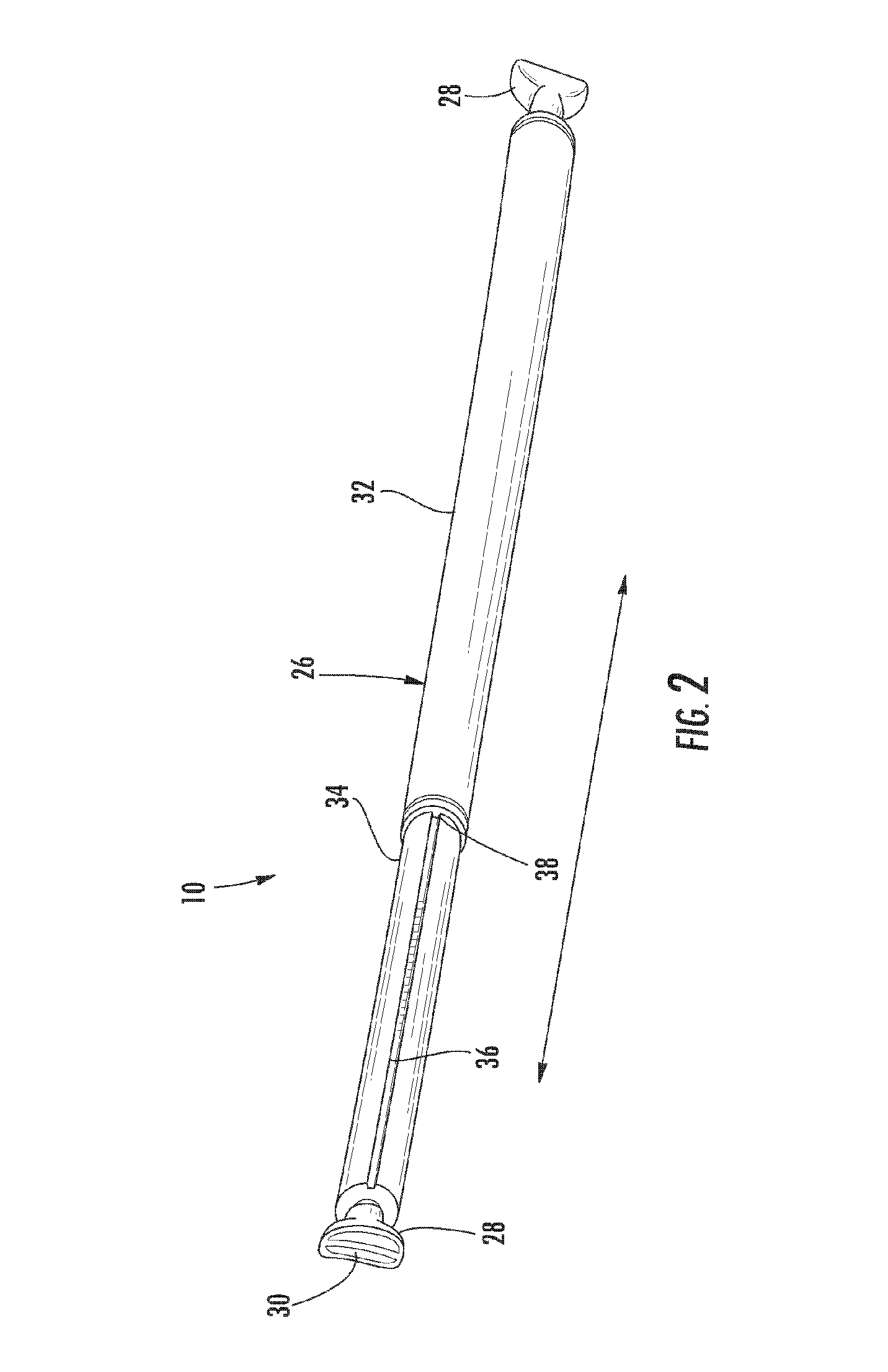
[0027]Turning now to FIG. 2, the...


PUM


Abstract

The adjustable tension shade includes a spring motor, an axle, and a shade roller. The spring motor is mounted to the axle and drives the shade roller. The axle has an adjustable telescoping shaft and the free ends of the axle are spring-biased outwardly away from each other. The shade roller has a tubular body that surrounds the axle and the spring motor and serves as a mounting point and storage unit for a shade. A pair of feet is connected to each end of the axle and each has a soft rubber gripping surface thereon.

Description

BACKGROUND OF THE INVENTION[0001]1. Field of the Invention[0002]The present invention generally relates to window shades. More specifically, the present invention relates to spring tension mounted window shades.[0003]2. Background of the Related Art[0004]In the home improvement and construction industries, there is a desire to make a window more pleasing to the eye, to provide some type of shade to the sun and to provide privacy, as needed. Windows are available in many different sizes thereby necessitating that the window shade be fit to the window casement at hand. As a result, numerous sizes of window shades must be available to fit a given window. This is particularly problematic in connection with the sale of such shades because different sizes of shades must be available for purchase to fit the different sizes of windows. Windows of uncommon sizes require custom built shades.[0005]In the prior art, there have been many attempts to address the problem of fitting a shade to a wi...

Claims


Application Information

Patent Timeline
Patent Type & Authority Patents(United States)
IPC IPC(8): A47K5/02
CPCE06B9/44
Inventor BIBBY, KEITHDOMINA, LYNN
Owner KENNEY MFG
Why Eureka
Try Eureka