Redundant architecture for brake-by-wire system

Active Publication Date: 2006-10-31
THE BF GOODRICH CO
View PDF9 Cites 37 Cited by
  • Summary
  • Abstract
  • Description
  • Claims
  • Application Information

AI Technical Summary

Benefits of technology

[0005]A redundant architecture for a brake-by-wire system is provided. The system includes a pressure source; at least one brake actuator for exerting a braking force on a wheel as a result of pressure provided by the pressure source; at least one servo valve for controlling an amount of pressure provided from the pressure source to the at least one brake actuator in response to a servo valve command signal; a shutoff valve in line with the at least one servo valve for preventing pressure from the pressure source from being provided to the at least one brake actuator i

Problems solved by technology

An aircraft presents a unique set of operational and safety issues.
For example, un

Method used


Image

  • Redundant architecture for brake-by-wire system
  • Redundant architecture for brake-by-wire system
  • Redundant architecture for brake-by-wire system

Examples


Embodiment Construction

[0012]The present invention will now be described with reference to the drawings, wherein like reference numerals are used to refer to like elements throughout.

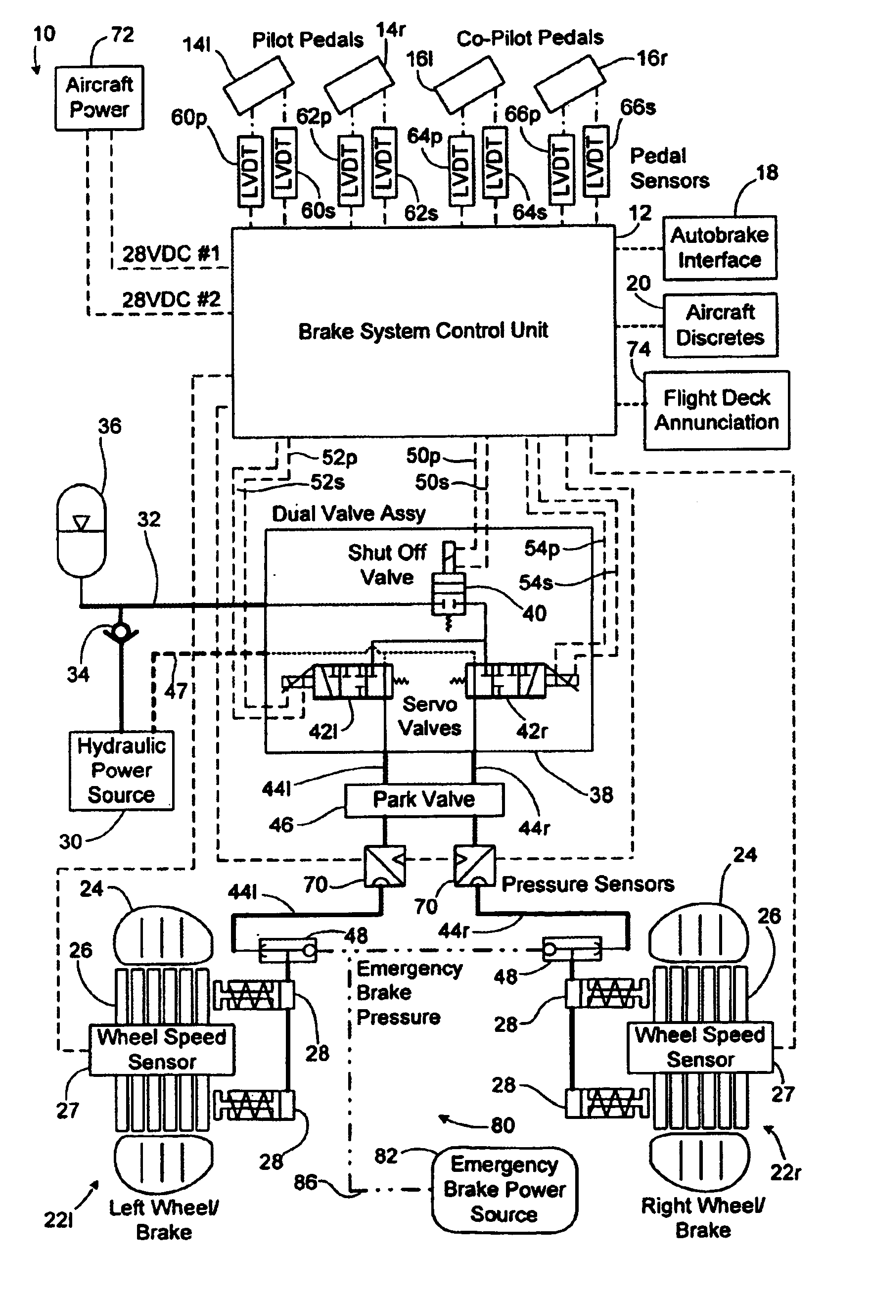
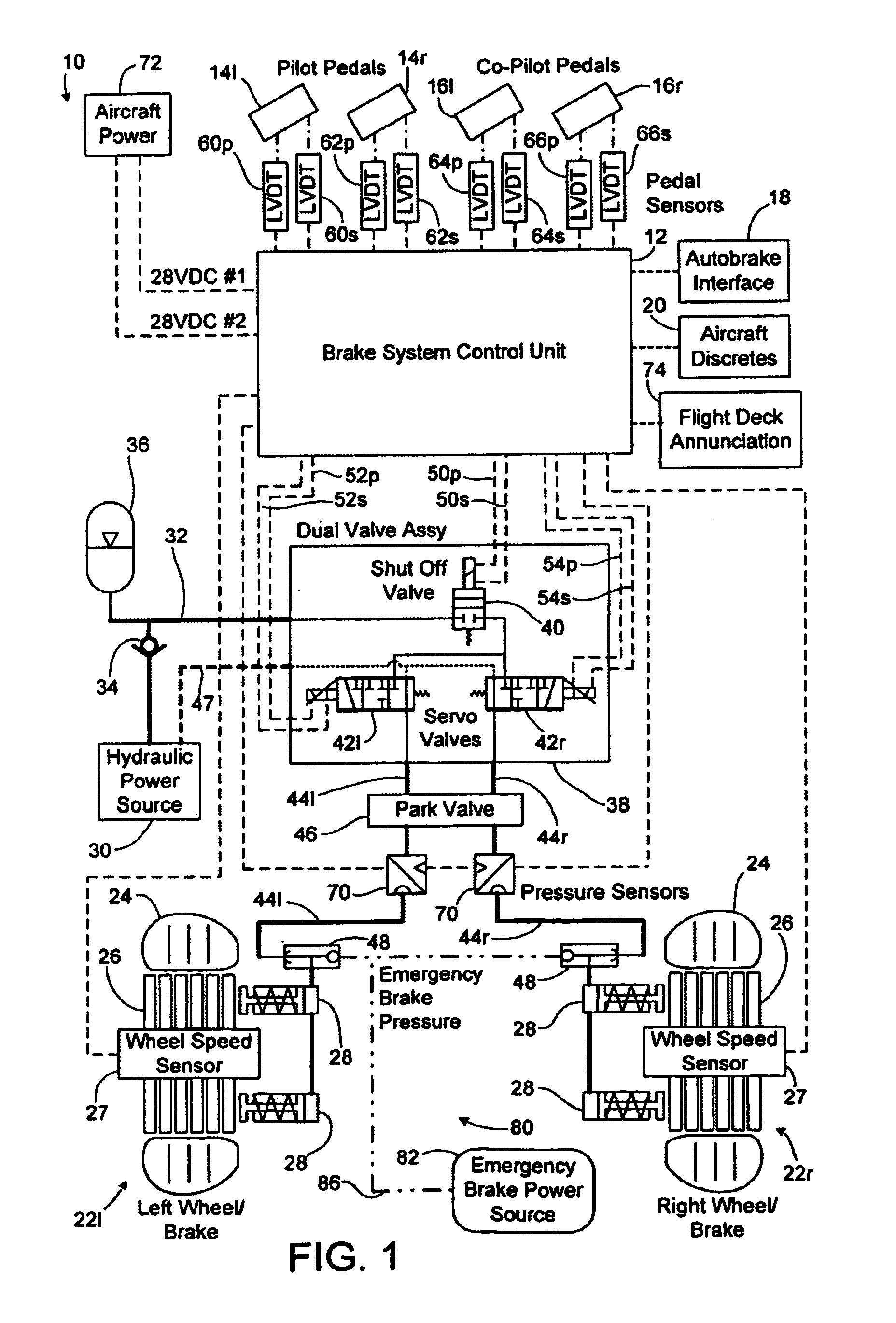
[0013]Referring to FIG. 1, a redundant braking system 10 is shown in accordance with one embodiment of the present invention. The braking system 10 includes a braking system control unit (BSCU) 12 which is programmed to control the various braking functions described herein. In the exemplary embodiment, the braking system 10 provides braking for an aircraft. However, it will be appreciated that the braking system 10 may be used in connection with other types of vehicles without departing from the scope of the invention.

[0014]The BSCU 12 receives brake command signals from left and right pilot brake pedals 14l and 14r, respectively, and left and right co-pilot brake pedals 16l and 16r, respectively. The brake command signals from the pilot and co-pilot brake pedals are indicative of a desired amount of braking as is convention...


PUM


Abstract

A redundant architecture for a brake-by-wire system is provided. The system includes a pressure source; at least one brake actuator for exerting a braking force on a wheel as a result of pressure provided by the pressure source; at least one servo valve for controlling an amount of pressure provided from the pressure source to the at least one brake actuator in response to a servo valve command signal; a shutoff valve in line with the at least one servo valve for preventing pressure from the pressure source from being provided to the at least one brake actuator in response to a shutoff valve command signal; a processor which executes code in order to carry out brake control operations, the processor outputting the servo command signal and the shutoff valve command signal in response to system inputs provided to the processor; a shutoff valve enable device for performing brake control operations redundant at least in part with the processor and based on the system inputs, and selectively enabling shutoff valve command signals from the processor to be provided to the shutoff valve based on the redundant brake control operations.

Description

TECHNICAL FIELD [0001]The present invention relates generally to brake systems for vehicles, and more particularly to brake-by-wire systems suitable for use in aircraft.BACKGROUND OF THE INVENTION [0002]Various types of braking systems are known. For example, hydraulic, pneumatic and electromechanical braking systems have been developed for different applications.[0003]An aircraft presents a unique set of operational and safety issues. For example, uncommanded braking due to failure can be catastrophic to an aircraft during takeoff. On the other hand, it is similarly necessary to have virtually fail-proof braking available when needed (e.g., during landing). Moreover, it is important that braking be effected promptly and reliably.[0004]In view of shortcomings associated with conventional braking systems, there is a strong need in the art for a braking system which may be employed more reliably on a vehicle such as an aircraft.SUMMARY OF THE INVENTION [0005]A redundant architecture f...

Claims


Application Information

Patent Timeline
IPC IPC(8): B60T7/00B60T7/12B60T8/17B60T8/32B64C25/42B64C25/44
CPCB60T8/1703B60T8/325B60T8/326B64C25/426B64C25/44B60T2270/82Y10S303/09
Inventor WILLIAMS, AARON CHARLESASH, BRYAN ANTHONYCONKLIN, PETER STANTONZWICK, DAVIDTOWNSEND, DAVID
Owner THE BF GOODRICH CO
Why Eureka
Try Eureka